Abstract
Demand for fast-cycle, dimensionally-consistent, thin wall parts molded from reinforced engineering thermoplastics continues to increase. The use of high strength, high thermal conductivity copper alloys has been limited by the perception that these alloys will not stand up to the wear of reinforced engineering resins. This is the second part of a discussion on the effects of erosive wear on copper alloy mold components. The ability of several chromes, electroless nickel, and titanium nitride to protect against erosion was tested. Several combinations of alloys and plating systems provided wear resistance that favorably compared to hardened H13 tool steel.
Introduction
Various types of platings and coatings have long been used to protect wear surfaces in an injection mold. These coatings have been used to resist two primary forces, wear and corrosion 1 . Since the majority of components in an injection mold are made from a variety of tool steel grades, the industry's understanding about which coatings work in what applications is based upon their capacity to protect steel. However, copper alloys continue to gain more acceptance as the logical choice to build cores and core-like structures in high-performance injection
Coatings currently used for injection molds include titanium nitride (TiN), electroless and electroplated hard nickel, standard industrial hard chrome, and a variety of enhanced chromes. Enhanced chromes include methods of changing the chrome's surface structure, chrome application density, or the addition of wear or lubrication enhancements either deposited during the plating process, or through some secondary process to fill the micro-cracks of the chrome surface. This is done because standard industrial hard chrome has a plate-like surface structure with tiny micro-cracks at the plate boundaries. Altering this structure, by filling the micro-cracking at the boundaries improves both corrosion and wear resistance.
Since it was not possible to research the effects of all the aforementioned platings and coatings on mold components made from copper alloys, a representative group of coatings was chosen in 1997 at the beginning of the wear study conducted at Western Michigan University. Since that time, more than 1.5 million cycles have been run in the pursuit of a better understanding of the relationship between base alloys, coating types, and types of wear. Certain aspects of the methodology for this study, as well as data for erosion of unplated copper and steel alloys were discussed in the companion paper Resistance to Erosive Wear by Copper Alloy Mold Components 3 . This work is presented as a two-part study, the authors strongly suggest that this paper be read prior to the interpretation or use of the data that follow. As with previous work at Western Michigan University, every effort has been made to reflect industrial operations without sacrificing the control normally associated with laboratory experimentation 4,5 .
Description of Equipment
Mold
The experiment used a geometrically balanced eight-cavity mold with edge gate .76 x .76 mm (.030" x .030") and minimal draft. A DME straight-shot hot sprue bushing was used. The mold had guided ejection and four mold interlocks. Both the A and B plates were cooled using ¼ NPT water lines configured in a single circuit around the perimeter of the tool. Four baffles on each side of the tool delivered water to the cavities. Coolant temperature was set to 17° C (65° F). The cores were cooled by a copper chill-plate mounted on the back of the tool.
Part
The parts were 1.5 mm (.06") thick round chips, 19 mm (.75") in diameter with a 5 mm (.20") high wall running around their diameter 2 . A flat was formed on the inside of each part by a flat cut into the core pin ( Figure 1). The wall thickness of the outside wall was reduced to .71 mm (.028) in the area of the flat. This flat was positioned directly opposite of the gate and was the first area of resin contact inside the cavity. Wear due to the flow of glass fibers was the focus of the erosive wear study.
Material
The material used in the study was 33% glass-filled Nylon 6 supplied by Honeywell/Allied Signal. This material was chosen as representative of the wear properties seen in most glass filled engineering resins. Prior to molding, the nylon was dried to .030% moisture content. An Arizona Instruments Max 2000 moisture analyzer was used to monitor moisture content before and after run. Shots that were not retained were ground by a nine-blade Conair auger-fed grinder with a screen size of 5 mm (3/16). After grinding, the resin was fed through a cascade aspirator to remove fines. Material conveyance was performed using AutoLoad vacuum accelerators.
Additional Equipment
All molding was conducted with a 77 metric ton (85-ton) VanDorn hydraulic toggle injection-molding machine having a 35 mm (1? ") diameter screw and a 20.6 cc (5 ounce) maximum shot size. An AEC mold temperature controller regulated mold coolant temperature. Coolant flow rate, input and output temperatures, and pressure loss was monitored in all cooling circuits.
Methodology
Many of the procedures used in this experiment are detailed in the aforementioned companion paper 3 . The experiment consisted of twenty base material and plating combinations including three copper alloy base materials, which were tested with and without platings. The platings were electroless nickel R c 50, titanium nitride R c 84, industrial hard chrome R c 66-70, Armoloy® TDC R c 72, and Armoloy XADC® R c 90. The copper alloys included C18000 R b 85-96, C17510 R b 95-100, and C17200 R c 34-40. The thickness of electroplating was .005mm (.0002) and the electroless coating thickness was .008mm (.0003). To establish a comparison to conventional tooling materials unplated P20 R c 32 and hardened H13 R c 54 were also tested.
Experimental Design and Measurement
Dependent variables in this study included the depth of wear measured at the point of resin impact ( Figure 1), the number of cycles, and visual observation (e.g. scratches, chips, etc.) made at the time of measurement. Independent variables included the core substrate material (base material) and the plating material. The most aggressive components of wear in the cavity were assumed to be the glass fibers present in the resin. Three generations of material were used (virgin, first, and second generation regrind).
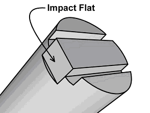 Figure 1. Core Pin Geometry
The data collection for plated copper alloy samples was done in the form of a screening experiment. Therefore a minimum number of samples were taken for each coated combination, in most cases two. The data were collected under rigorous laboratory conditions. Six samples of the unplated copper alloys and P20 were tested, while four samples of H13 were tested. The failure criteria was defined as .005 mm (.0002) of erosive wear on the impact flat across from the gate. All data were generated under high shear conditions 6 . Both a custom-build gage and a WYCO interference microscope were used to collect measurement 3 .
Findings
Two things are of interest when reviewing these data. First is the relative ranking of the various hard coatings, and second is the affinity of a given hard coating or group of coatings to adhere to a base substrate. In Figure 2 it can be noted that the two of the four top performers had XADC plating applied to them. XADC was observed to be more consistent in its performance on both of the softer alloy grades (C18000 and C17510). A significant difference (p<.05) was measured between the top four plated combinations and all other combinations ( Table 1). In other words the other hard coatings have overlapping data sets. Hardened H-13 was shown to have a significant difference (p<.05) from both groups of combinations.
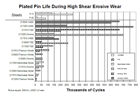 Figure 2. Comparison of Core Pin Life
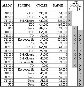 |
Titanium nitride rapidly flaked off the C17200 base alloy. It was initially thought that the reason for poor performance in the first sample run was that a high temperature TiN had been used. When the sample was hardness tested after plating it was found that the hardness level of the base alloy had been substantially reduced as the TiN process overaged the sample. The second sample run on this alloy was done using the low temperature method. However, these two samples produced consistent data. The low temperature method provided uniform looking samples at the outset, but the samples failed to perform better than the high temperature method. In both cases, their plated performance is below that of the unplated samples 3 .
The final type of plating reviewed here is electroless nickel. Overall electroless nickel performed in a consistent way. Electroless nickel, because it is a non-electroplating process, provided a more uniform deposition than the electroplated chromes. In addition, electroless nickel did not chip at sharp corners as did titanium nitride and the three of the chromes. Figure 3 shows an example of the chipping seen in this study. Dog bones or chrome trees that result from increased deposition at outside sharp corners are visible in the photograph 7 . Chipping is important since removal of the platings from sharp corners in the molds could either fail the component or speed up the wear process.
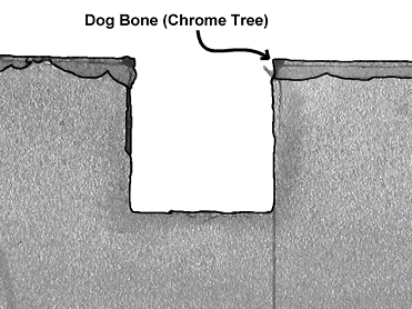 Figure 3. Chipping of Plating
As seen in Figure 4, a threshold wear effect is seen on a plated surface in erosion. The shallow sloped area of the curve is the wear period prior to removal of the hard coating. The threshold is the point at which the hard coating, or plating, is worn through. The second phase of wear is that a much steeper curve represents the identical slope angle to the base material in question 4 . Therefore, once the plating is removed, the wear continues at a rate that would be normal for an unplated component.
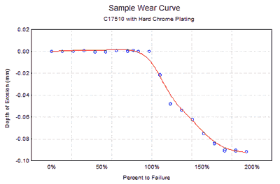 Figure 4. Sample Wear Rate Curve
Conclusions
The top performing combinations had one of the three chrome platings applied to them. Although electroless nickel performance was lower than that of the chromes, there was the absence of chipping on sharp corners of the components which was seen on most of the chrome samples. Coating retention may make electroless nickel a better choice for mold components with complex geometries.
Titanium nitride's performance shortened the life expectancy of C17200 when compared with the unplated samples. As noted earlier, two methods of titanium nitride were used, both a high temperature method, and a low temperature method. The high temperature method is applied above the overaging temperature of the alloy. Therefore, it reduced the base hardness of C17200 alloy. When the titanium nitride failed, it tended to chip off the surface because it is such a hard material (R c 84). In one case the chips embedded in an injector sleeve and ruined the both core and the sleeve.
Overall it is clear that hard coatings, especially chrome-based coatings, provide performance in erosion resistance comparable to, or better than, one would expect from hardened H13. Hardened H13 is the standard in the mold building industry where a hardened core is required. It stands to reason that appropriate plating of any of the three copper alloys should provide longevity and allow the molder to utilize the benefits of copper alloys, both in terms of reduced cycle time and improved product quality. Even when using reinforced engineering thermoplastics.
The relative life of any plating/substrate combination depends upon the following: design of the plated component, metallurgy of the substrate, composition of the exact plating applied, plating techniques, and work methods. It is the recommendation of the research team that identification of a plater who is both skilled at plating mold components and has familiarity with plating materials other than steel is important. This should provide the molder and mold builder with the best assurance of a high performance plated surface.
Acknowledgements
The authors extend their thanks to the Copper Development Association Inc. and its members for providing necessary support for this research. Performance Alloys & Services Inc., PCS company and Johnson Precision Mold and Engineering constructed mold components. Ampco Metals Inc., BrushWellman Inc., Copper and Brass Sales, and NGK Metals provided alloys for the mold. Armoloy of Illinois, Halechrome and Balzers, Inc. provided the platings in this study. Honeywell/Allied Signal provided the nylon 6. Research assistance was provided by the WMU Tribology Laboratory, Dr. Dale Peters and Dr. Harold Michels of the Copper Development Association Inc.
Each of the following students invested 250-400 hours toward the completion of this research: Kevin Andruszkiewicz, Eric Burgess, Eric Grant, Carlene Harris, Dennis Creedon, Thomas Hall, Leslie Shaw, Gregory Snitgen, Alicia Habercorn, Allen Woodruff, Ryan Brill, Jared Patterson, Troy Winningham, Rich Brothers, Adrian Sultana, Frank Asher, Mike Buckle, Jeff Lewis, Marshall Proulx, Jen Vanover, Leonid Fedorovitch, Keith Wilkenson, Mike Westra, Damian Garland, and Deb Wilde.

References
- Buckleitner, E. V. (1995). Plastics Mold Engineering Handbook, 5th ed. , Chapman & Hall.
- Engelmann, P., Dawkins, E., Shoemaker, J., Monfore, M. (1997). Improved product quality and cycle times using copper alloy mold cores. Journal of Injection Molding Technology , vol. 1 (1), pp. 18-24.
- Hayden, K., Engelmann, P., Guichelaar, P., Dealey, R., & Monfore, M. (2001). Resistance to erosive wear by copper alloy mold components. Technical Papers , vol. 47, pp., Brookfield, CT: SPE.
- Engelmann, P., Hayden, K., Dealey, R., & Monfore, M. (2000). Understanding wear mechanisms: the key to mold life. Technical Papers , vol. 46, pp. 952-956, Brookfield, CT: SPE.
- Engelmann, P., Dawkins, E., Shoemaker, J., Monfore, M. (1997). Improved product quality and cycle times using copper alloy mold cores. Journal of Injection Molding Technology , vol. 1 (1), pp. 18-24.
- Engelmann, P. & Dealey, R. (2000, January). Injection mold design guidelines: Maximizing performance using copper alloys - Part eight in a series. Modern Mold and Tooling , pp. 49-52.
- Hayden, K., Engelmann, P., Dealey, R., & Monfore, M. (1999). Mold wear vs. wall thickness: Critical information for thin wall molding. Technical Papers , vol. 45, pp. 1063-1067, Brookfield, CT: SPE.