- Shared Tower, Two Grounding Systems
- Extensive Upgrade
- Protection in Depth
- More Copper Indoors
- Code-Acceptable, But Not Good Enough for Winter Park
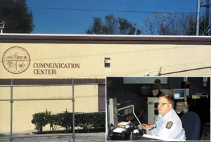 The Winter Park, Florida Communication Center provides police, fire and 911 services to a community of 23,000 inhabitants. Because the center is located in Florida's "Lightning Alley," city officials upgraded its lightning protection/grounding system with additional electrodes, a 4/0 ring-ground, 4/0 halo grounds and an extensive network of heavy-gage copper grounding conductors.
In Winter Park, the most serious threat to reliable communications is weather. The city is located in Florida's "Lightning Alley," where more than 100 days with thunderstorms can be expected annually. Any one of those storms could disrupt or destroy the city's communications system just when it might be most urgently needed.
To reduce weather-related threats to its emergency response system, Winter Park houses its Communication Center in a 2000-sq ft (200-sq m) reinforced concrete building . Both the building and its 90-ft (27-m) antenna tower (Figure 1) can withstand 200-mph (322 km/h) winds. The Communication Center and antenna tower are also equipped with a lightning protection/grounding system. The system initially installed when the facility was built has been extensively upgraded to ensure maximum reliability. This article describes the important role copper played in the upgraded system.
Back to TopShared Tower, Two Grounding Systems
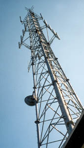 Figure 1. The Communication Center shares its 90-ft antenna tower with a cellular telephone/long-distance service provider. Both tenants maintain their own lightning protection/grounding systems. Of the two systems, the Communication Center's is far more extensive and considerably more robust.
The Communication Center shares its antenna tower with a cellular-phone/long-distance service provider. The telephone company built the tower on the municipally-owned site, basing its lightning protection/grounding system on its own and telephone-industry specifications, in this case grounding the structure through reinforcing rods in the concrete footers. This system, known as a Ufer ground, is listed under the National Electrical Code® (NEC) as an acceptable grounding method.
The telephone company houses its switches and communications equipment in a nearby modular building, separate from the Communication Center. The two buildings have separate electrical hook-ups and therefore require separate grounding systems. Thus, both the telephone company's building and the Communication Center have their own primary grounding electrodes; the Comm Center's is a copper-clad rod driven near the building's service entrance panel.
The original lightning protection/grounding system was designed and installed according to the NEC. However, according to Joe Serrano, Winter Park's Director of Communication, "We knew there would always be a potential risk for serious damage, and because of that risk, and the fact that our dispatchers routinely deal with life-critical situations, we decided to upgrade our center with the most reliable grounding and lightning protection system available."
Serrano called in Power & Systems Innovations, Inc. (PSI) an electrical design firm located in Orlando. John West, the firm's founder and president, has gained a strong reputation for providing reliable lightning protection and grounding systems to facilities such as hospitals, banks, airports and military bases, plus a number of "sensitive" government installations.
John West had a very personal reason to give Winter Park the most reliable system available. As he puts it: "My parents live in Winter Park. They are over 80 years old and might need 911 assistance one day. I made absolutely certain this facility would be safe from lightning damage!". Back to Top
Extensive Upgrade
West began with the tower's grounding system. In place of the #2 AWG conductors the telephone service used to ground its coax cables (See "Code-Acceptable, But Not Good Enough for Winter Park" article below), West installed #29X tinned copper lightning cable and 4/0 copper. (Lightning cable is a hollow braided conductor that resembles a Chinese finger trap toy.)
For each coax cable, West split a length of the lightning cable, wrapped it around an exposed portion of coax shield, soldered it in place and clamped and re-insulated the assembly (Figure 2-A). West next soldered the lightning cable to lengths of 4/0 copper, then bonded the 4/0 to a short horizontal bus mounted on a nearby cable tray (Figure 2-B). From there, he bonded to a vertical length of bare 4/0 copper, running the 4/0 straight down to a new grounding electrode driven directly below (Figure 2-C).
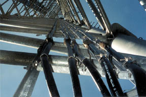 Figure 2-A
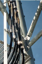 Figure 2-B
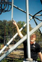 Figure 2-C
Bonds to the coax shields were made above the point where the cables take a 90° turn toward the Comm Center building. West recommends this practice. "If a lightning strike were to come down the cable shield and encounter a turn in the cable, it could either follow the cable toward the building or continue in a straight-line path to earth. By grounding the cable shield above the bend, we increase the odds that the strike will continue straight downward.
"For extra protection," West continued, "we also bond to the coax shield at the point where it enters the building (Figure 3). We first mounted a 1/4-in (6.4-mm) thick copper grounding plate to the building wall. The plate has cutouts for the coax to pass through. We exposed a section of cable shield and bonded it to the plate. Then we bonded the plate to the building's grounding system using a vertical length of 4/0."
"We also wanted to improve on the tower's Ufer ground (Figure 4), originally installed by the phone company, so we drove two more electrodes on diagonals leading outward from each of the tower's legs. Those electrodes form what is called a star-ground. We used bare 4/0 copper to connect all electrodes. We then bonded a lead from the nine new electrodes to the Center's primary electrode, which is located below the service entrance panel. The entire system has a ground resistance of less than four ohms."
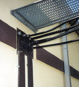 Figure 3. Coax cables enter the Communication Center through a 1/4-in (6.4-mm) thick copper plate mounted on an exterior wall. The cables' shields are bonded to the plate. The plate itself is connected to a buried ring-ground by the bare 4/0 copper cable visible at the left side of the plate.
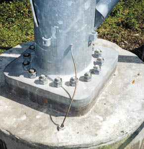 Figure 4. The antenna tower was grounded during construction using #2 AWG bare copper bonded to reinforcing rods in the footers (Ufer grounds). PSI augmented this system by bonding each of the tower's four legs to two electrodes (not shown) driven on diagonals extending outward from the tower. The new grounding-electrode conductors are bare 4/0 copper.
Why a star ground for the tower? "Current flow from a lightning strike tends to spread outward when it enters the ground," West explained. "By locating the tower's grounding electrodes on diagonals and connecting them with heavy-gage copper, we help dissipate the charge into the ground and away from the building we want to protect."
Back to TopProtection in Depth
West next drove a series of electrodes around the Comm Center at 20-ft (6-m) intervals. The electrodes were bonded to a 4/0 copper ring-ground connected to the primary grounding electrode at the service entrance. Additional 4/0 cables were installed from the ring-ground to all metal objects on or near the building's exterior: electrical panels, sub-panels, a chain-link fence and even metal downspouts (Figure 5).
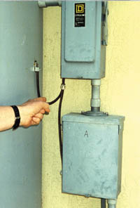 Figure 5-A
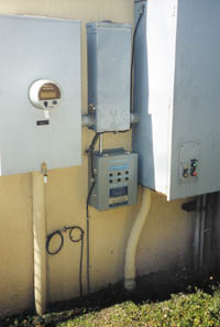 Figure 5-B
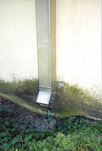 Figure 5-C
The Center's emergency power generator is connected to the ring-ground with 4/0 copper. An additional ground connection is made from the generator frame to reinforcing rods in the concrete pedestal on which the generator stands (Figure 6).
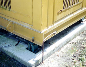 Figure 6. The emergency generator is also connected to the ring-ground, and is additionally grounded to reinforcing rods in its concrete pad.
West installed additional lightning protection in the form of high-capacity transient voltage surge suppressors (TVSSs). "We strongly recommend that our clients install a TVSS at the service entrance and at all critical sub-panels. If the facility contains sensitive electronic equipment, we also recommend they install a TVSS for each branch circuit. That gives you three layers of protection. TVSS units are reliable, not expensive and easy to install."
Back to TopMore Copper Indoors
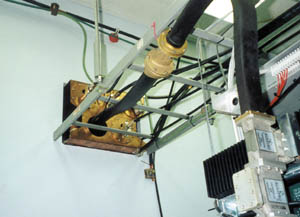 Figure 7.Coax cables enter the Communication Center through a fabricated copper grounding plate. Waveguides (light-colored connector and black rectangular shape to the right) connect to communications equipment. The grounding plate is bonded to a 4/0 copper halo ground that circles the room near the ceiling (black cable, top of photo).
Indoors, cables from both penetrations are bonded to halo grounds surrounding each room, approximately six inches (150 mm) below the ceiling. The building's original grounding system already contained halo grounds constructed from #6 AWG conductor. West overlaid a second halo in 4/0 copper, running it in parallel with the existing installation.
More 4/0 copper connects the halo grounds to the equipment racks that crowd several of the facility's rooms (Figure 8). At first glance, the cables appear to be rather loosely draped, but West explains that this arrangement is intentional. "Recommended practice calls for bends in lightning protection/grounding conductors to have generous radii, with no sharp bends. This is particularly valuable where high frequencies such as those associated with communications equipment, or lightning, are involved."
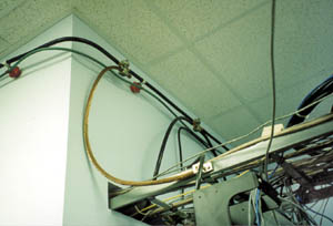 Figure 8. The new halo ground connects to equipment racks with bare 4/0 copper and tinned copper lugs. Note generous bend radii at all turns and corners. Large radii are recommended for grounding conductors in situations where HF signals are present. PSI left an existing halo ground in place (green #6 AWG cable, top of photo).
Joints between sections of the fabricated equipment racks are jumpered with short lengths of #2 AWG copper (Figure 10). These connections ensure that all equipment connected to the racks see the same low ground potential.
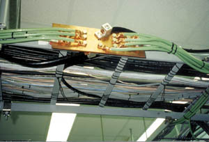 Figure 9. Grounding jumpers from individual equipment consoles (green #2 AWG cables) connect at several 1/4-in (6.4-mm) thick copper bus plates mounted on equipment racks. Insulated 4/0 copper cables lead from these plates to the 4/0 halo ground and from there to the main grounding connection at the service entrance panel.
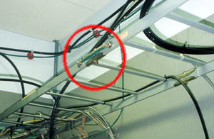 Figure 10. Joints between sections of equipment racks are jumpered with copper conductors. Such connections provide electrical continuity and ensure that all connected equipment sees the same low ground potential.
Finally, grounding connections in the Center's dispatch room are made beneath the room's raised floor. A signal reference grid was not considered necessary here, so West home-runned grounding jumpers from each equipment console to a 4/0 cable leading to the building's grounding system. Jumpers are made from insulated #2 AWG copper; as was done elsewhere in the Center, all grounding connections in the dispatch room are made with bolt-on copper-base lugs
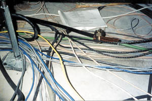 Figure 11. Grounding connections in the dispatch room are made beneath the floor to reduce clutter. Here, a 4/0 copper grounding conductor leading to the service entrance (black cable, top center) connects with #2 AWG leads (green cable) that extend to the dispatchers' consoles and other equipment in the room.
With its ring-ground, multiple grounding electrodes, TVSSs and reliable copper connections, the Winter Park Communication Center certainly has one of "the most reliable grounding and lightning protection systems available," as Joe Serrano puts it. And even when one of Florida's famous thunderstorms rumbles by, the good citizens of Winter Park, including John West's parents, can sleep soundly knowing that their city's emergency response system will remain securely on-line.
Back to TopCode-Acceptable, But Not Good Enough for Winter Park
The original grounding/lightning protection system installed at the Winter Park Communication Center was designed by the cellular-phone/long-distance telephone service provider with whom Winter Park shares the 90-ft antenna tower. Grounding connections at the telephone company's side of the tower illustrate some of the reasons why Winter Park officials upgraded their equipment despite the fact that the system shown here meets telephone company specifications and is in accordance with the National Electrical Code®.
Grounding connections to coax cable shield at the telephone service provider that shares Winter Park's antenna tower are made on the horizontal run of the cables as they enter the service provider's building (Figure 12). Such connections are not as protective as those on the Communication Center's system, shown in Figure 2. In addition, grounding electrode conductors installed by the telephone company are #2 AWG. For better protection against lightning damage and to ensure a low-impedance ground connection, the Communication Center's facilities utilize robust 4/0 copper grounding electrode conductors.
A grounding connection to the telephone company's building was made at a lifting lug on the modular structure (Figure 13). Grounding of this sort may serve no purpose at all if, in fact, the lifting lug is not actually bonded to a structural metal frame.
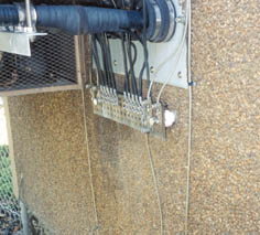 Figure 12. Grounding connections to coax cable shields at the cellular-telephone/long-distance service provider that shares Winter Park's antenna tower are made on the horizontal run of the cables. Connection to vertical runs provide better lightning protection, according to PSI's John West. #2 AWG grounding electrode conductors installed by the telephone company are the minimum size permitted under the NEC. The Winter Park Communication Center up-sized its grounding electrode conductors to more-robust 4/0 copper.
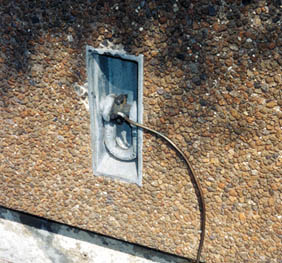 Figure 13. Grounding connection to a lifting lug on the telephone provider's modular building. There is no assurance that the lifting lug is actually bonded to the structure's metal frame.
The Principals
 John West, Sr. is President of Power & Systems Innovations, Inc. (PSI), Orlando, Florida. Founded in 1992, Power & System Innovations, Inc (PSI) provides products, services and consulting related to power quality, power protection, surge protection, grounding, lightning protection and other anomalies that can damage equipment and/or cause data loss. PSI provides-on site consulting services. In addition, the company designs, installs and services a broad range of protection equipment and systems. Further information about psi can be found at the company's web site, http://www.psihq.com, or by calling them at (407) 380-9200 or (800) 260-2259.
 Joe Serrano, Director of the Winter Park, Florida Communication Center. The center provides police, fire, emergency response and 911 service to the City of Winter Park and surrounding communities. Mr. Serrano was convinced that upgrading the Communication Center's lightning protection/grounding system with additional electrodes and heavy-gage copper conductors would increase the level of protection for the Center's valuable equipment, providing a higher level of safety to the community.