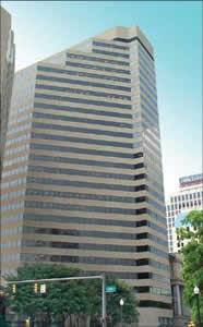
 Caveat emptor - Let the buyer beware! Good advice, whether you're buying a used car or dealing with highend commercial property. Case in point: Capitol Square, an attractive 27-story, 400,000-sq ft office tower located in downtown Columbus, Ohio ( right photo). Built in 1982, Capitol Square and its electrical system served its early occupants well. Until, that is, growing loads and some false economizing taken at the time of construction caught up with the original system.
By the time the firm of Jones Lang LaSalle (JLL) took over management of the property for its owner in 1998, the old wiring system had begun to cause noticeable problems. Noah Gens, JLL's vice president for leasing and management, recalls: I could count on it. The problem would begin on the 27th floor. Every Friday afternoon, a fuse would blow or a breaker would trip at around 2:00 pm, and all lines that were fed from that floor would lose one of the three phases. We'd have to take part of the building down and, because of the way it's wired, maybe half the building would be down for several hours.
Growing loads were part of the problem. The building was constructed for a power load of 3 W/sq ft, explains Gens. Today, we have a tenant who wants 8 W/sq ft for general- service loads (including computers) and 4.5 W/sq ft for heating and lighting.
Another problem was lack of control over electrical work performed under earlier building management companies. According to Ken Kuzma, JLL's property manager and chief engineer, The original electrical contractor was out of business, and several other contractors had done work under previous owners. Some tenants brought in their own electricians and never told facilities management what they'd done, so we had to start solving the problems from scratch.
First Step: System Audit
JLL, one of the world's leading real estate services and investment management organizations, wanted a thorough audit of the building's electrical infrastructure. Another JLL client recommended PowerEdge Technologies, Inc. a Canton, Ohio-based consulting and engineering firm with a reputation for solving power quality issues. PowerEdge sent Tim Cookson, an electrical engineer and a certified power quality specialist. Cookson went over Capitol Square's electrical system from top to bottom. The discrepancies he discovered can be found in many older
buildings maybe yours.
Cookson describes the system: Capitol Square has three 480-V substations: two at 3,000 A and one at 4,000 A. The two smaller feeds are used to supply low-voltage service in the building: one for floors 116 and one for floors 1727. The problems with tripping breakers and open fuses occurred on the upper-floor service, so that's where we started work, but we also found problems on the lower floors.
 Figure 1. Partial schematic plan of electrical systems at Capitol Square. Note how feeder sizes to lower floors were reduced as the project rose (service #1, left). Panels for services #2 and #3 are located on the 27th floor; they then supply loads located below them, in some cases in the basement.
Low-voltage service to the upper floors, designated as service #2, is supplied by a 1,350 A/480-V copper bus duct from the basement to the 27th floor ( Figures 1 and 2). There, it feeds a 300-kVA step-down transformer that supplies 208Y/120-V service back down to floors 17 through 27 ( Figure 3). The transformer was overheating so badly that building maintenance had to set up a large fan to cool it.
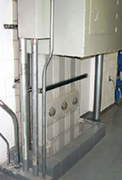 Figure 2. A 1,350-A/480-V copper bus duct leading from the Capitol Square basement to the building's utility loft on the 27th floor, from where it feeds the 300-kVA transformer that supplies 208Y/120-V service to the 17th through 27th floors. Aluminum feeder cables had loose connections, which contributed to the voltage drop experienced on the upper floors.
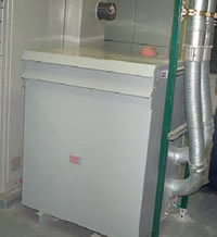 Figure 3. A 300-kVA transformer located on the building's 27th floor supplies 3-phase 208Y/120-V low-voltage service to floors 17 through 27. Poorly made high-resistance connections to the transformer caused large current differences on parallel conductors leading from the transformer. Loose connections on aluminum feeder cable throughout the system caused the transformer to overheat.
Feeders from the transformer to the floors below were wired with 4/0 aluminum. The aluminum conductor wasn't supported with wedges, as required, but that was just one of several problems. The 208Y/120-V service is three-phase, to which someone had apparently added an AWG #6 copper equipment grounding conductor as an afterthought because the green wire was run outside the conduit ( Figure 4). Equipment grounding conductors are required to be installed in the same conduit as circuit conductors.
Transitions from aluminum to copper on floors 17 through 26 were made improperly ( Figure 5), and many of the connections were loose. We picked up a lot of hot spots when we checked the panels with our infrared (IR) scanner. The loose connections caused voltage to drop to as low as 102 V on the upper floors during peak loading. The upper floor feeders were fused at 140 A, which is consistent with the aluminum wire originally installed, but when fuses kept opening, someone simply increased the fuse size to 200 A!
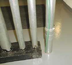 Figure 4. During an earlier undocumented fix, a green wire had been run outside conduit carrying 208Y/120-V, 3-phase power from the 27th floor to floors 1727. Replacement of aluminum feeder cables in the conduit with copper of the same gage left sufficient room to pull the green wire and an IG conductor inside the conduit. This avoided replacing the conduit, an expensive job.
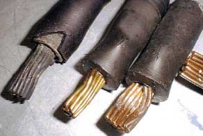 Figure 5. Many instances of improper connections between 4/0 aluminum feeder cables and copper breaker terminations on floors 1727 caused the aluminum to overheat, damaging the insulation. High resistance contributed to large voltage drops on these floors.
Breaker cabinets on floors 17 through 26 also contained improper neutral-ground connections ( Figure 6). Compounding this Code violation, someone had added a connection from all the N-G busses to building steel.
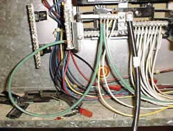 Figure 6. Inspection revealed that neutralground bonds had been made in all low-voltage breaker cabinets on floors 1726. Such bonds belong only in the service entrance panel. In addition, grounding conductors had been run from the panels to building steel, compounding the error.
 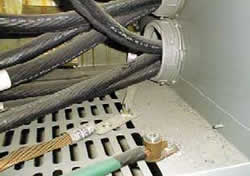 Figure 7. Improper grounding and bonding methods had been used inside the 300-kVA transformer. Both the grounding electrode conductor and the neutral-ground bond were connected to painted surfaces, and no equipment grounding conductor was present.
 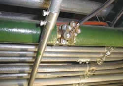 Figure 8. Improper grounding connection made to an interior facility water pipe located on the 27th floor. Such connections must be made to the main water service, and a jumper must be installed across the water meter. Neither of those connections had been made.
We also measured unusually high differences in current draw on parallel aluminum conductors leading from the 27thfloor 300-kVA transformer; as high as 62 A on phase A, 108 A on phase B and 29 A on phase C. That was clear evidence of poor (high resistance) aluminum connections at the transformer and/or switchboard. We also found that improper grounding and bonding methods had been used in the transformer. Both the grounding electrode conductor and the neutral- ground connection had been made to a painted surface inside the transformer case ( Figure 7). Painted surfaces offer questionable resistance and reliability, the last things you'd want at a grounding connection. And, neutral-ground bonds belong at the service entrance or at a separately derived source (transformer), nowhere else.
Low-voltage service to floors 1 through 16 was in better shape than that on floors 1727. For one thing, they were all copper. But we discovered that the original contractor had cut some corners, even on the service to the lower floors. The #1 low-voltage service was brought up in six risers. On the south wing side, 500-kcmil copper fused at 300 A had been run up to the sixth floor. But then, the feeder size was reduced to 300-kcmil for supplying the same floors on the north wing. The feeder size was reduced yet again for floors 7 through 11 and 12 through 16, where 2/0 (175-A fuse) risers were installed. When I see a situation like that, I suspect the builder was trying to reduce costs as the project went along. It's really false economy, because cutting corners doesn't leave any margin for error, and that was exactly what happened at Capitol Square.
Cookson found that the building's grounding system consisted of a connection to the utility ground and another one to an interior water pipe ( Figure 8). No connection had been made to the main water service. The interior water pipe connection was questionable, because the meter hadn't been jumpered as required by Code. The building also had a socalled isolated ground (IG); so-called in that it was connected directly to building steel on all floors, so it wasn't isolated at all. Like any modern office tower, Capitol Square contains a lot of computers and other sensitive equipment that need good grounding. It didn't have it.
Back to TopSafety and Grounding Fixed First
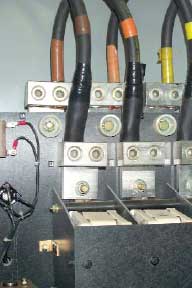 Figure 9. New, correctly installed copper feeder connections inside a breaker panel. Note that connections are now properly bonded at tinned-copper connector bars. Compare this installation with the cables shown in Figure 5.
We also called for two new 100-A breaker cabinets at each floor for the tenant who wanted 8 W/sq ft. The cabinets use bolt-in type circuit breakers with copper busses and terminal bars. Since we were now working with copper conductors, reliable bonds could be made inside the cabinets ( Figure 9). We corrected the poor connections at the transformer and eliminated the imbalanced parallel-phase currents. Improper neutral-ground bonds were removed. The 300-kVA transformer now runs at an acceptable temperature.
We had the contractor drive a low-resistance ground rod at the service entrance, bonding it to the new neutral-ground bus connections. We also bonded the grounding system to the main water service and jumpered the meter and main valve assemblies. Lastly, we bonded the grounding system to building steel. When the contractor finished work, Capitol Square had a low-resistance, better-than-Code-minimum grounding system.
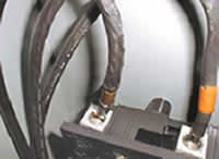 Figure 10. Evidence of overheating is seen in the damaged insulation on this aluminum conductor leading to the chiller disconnect switch on the building's 27th floor. The aluminum has been replaced with copper of the same wire gage.
Back to Top
More to Come
The retrofit isn't finished yet. Cookson continues to monitor breaker panels for hot spots, and he periodically checks and records loads at the transformers. He hasn't detected one sign of trouble so far, and those annoying outages have stopped completely. Perhaps even more important, Cookson is now writing a power management document for the entire building. It will contain specifications requiring permits for all electrical work by outside contractors. All prints must be submitted to JLL and approved before work begins.
Specifications will also include power factor and harmonicscontrol requirements. And, says Cookson, they will call for 100% copper conductors and listed copper lugs and connectors whenever any new circuits are installed. The specifications could become a model for other properties managed by JLL.
Are Gens and Kuzma pleased with the retrofit? Absolutely! says Gens. We haven't had a breaker trip or a fuse open since the retrofit. Power costs are down, our tenants are happy, and Ken and I can finally look forward to Friday afternoon.
The Principals
 Noah B. Gens is vice president, leasing and management, for Jones Lang LaSalle™, whose investment management business is one of the world's largest, with more than $20 billion under management. Additional information about Jones Lang LaSalle can be found at their Web site. Mr. Gens can be reached at (614) 464-2677 and at [email protected].
 Kenneth Kuzma is property manager/ senior chief engineer, leasing and management, Jones Lang LaSalle. Along with Mr. Gens, he has had primary responsibility for correcting deficiencies in Capitol Square's electrical and grounding systems since JLL assumed management of the building in 1998. Mr. Kuzma can be reached at (614) 464-2677 and at [email protected].
 Tim Cookson CPQ, PAE, is a senior electrical engineer with PowerEdge Technologies, Inc., a Canton, Ohio based firm specializing in power quality issues, including power quality and power management surveys, harmonic assessments, grounding and electrical system testing, operating environment assessments and site planning services for sensitive electronic equipment. The company also provides educational services to industrial, trade and educational organizations. For further information about PowerEdge Technologies and its services, call (330) 494-7314, fax (330) 494-7750 or visit their Web site.