- Tornado Alley Weather
- Grounding Expert Spots Targets for Upgrades
- Wet Soil Doesn"t Always Mean Low Resistance
- Cheap Insurance
- No More Equipment Damage, Signal Quality Improves
- The Bottom Line
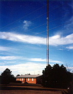 FM Station KROA, with studios, transmitter and 500-ft antenna tower in Doniphan, NE. Towers such as this are frequently struck by lightning. They must be correctly grounded to ensure personnel safety and to avoid equipment damage.
One station knows these hazards all too well. KROA, a 100-kW FM station with studios and tower in Doniphan, Nebraska, learned first-hand what happens when lightning strikesand where the lightning goes if the tower it strikes is connected to high-resistance ground.
Tornado Alley Weather
Doniphan lies in the Platte River floodplain, 130 miles west of Omaha and smack in the middle of Tornado Alley. Scores of thunderstorms blow through between March and August, giving the region an unenviable classification as being "lightning-prone." Not surprisingly, the local utility’s transmission and distribution lines have suffered plenty of lightning hits over the years, and high-intensity voltage surges to customers" circuits are not uncommon.
KROA’s studio-transmitter-tower complex is situated at the extremity of the local power grid. Overhead power lines terminate at a pole on the station’s property (Figure 1). The pole is fitted with a primary lightning arrester and a conventional utility-type grounding system consisting of a #6 AWG copper down-conductor connected to a 10-ft (3-m) copper-clad electrode. When lightning strikes nearby, surge current on the utility lines should find a natural path to ground via that electrode. That doesnt always happen, however, possibly because of the electrode system relatively high resistance to ground. As a result, voltage surges often spill over into KROA’s service entrance.
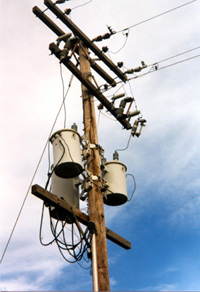 Figure 1. Power line terminus and transformers serving KROA. The pole is grounded with a 10-ft-deep grounding electrode, but because the electrode’s ground resistance is relatively high, surges due to lightning strikes on upstream power lines can pass to the station’s studios, where a lower-resistance electrode provides a better path to earth. It is important that the station have good surge protection at the service entrance and that the surge protection device itself be properly grounded.
FM antenna towers and the guy wires that support them are always grounded (unlike AM towers, which are insulated structures). Thus, a lightning strike to an FM tower would normally flow to earth through the grounding system. Unfortunately, lightning often branches out in unpredictable directions as it seeks the lowest-resistance ground path. In one memorable instance at KROA, lightning ignored the existing grounding system and instead followed the coaxial cable directly into the transmitter room. The hit destroyed expensive equipment, taking the station off the air for several weeks. Luckily, no one was injured but the incident was a strong indication that the grounding system should be improved.
At about the same time KROA was experiencing its lightning-related difficulties, station engineers noticed that there were also problems with the station’s signal quality. A constant "white" background noise could be heard behind the station’s transmission. A similar white noise was heard on telephone sets in the building. Could this noise and the recurrent threat of lightning damage be related?
Back to TopGrounding Expert Spots Targets for Upgrades
KROA called in Computer Power & Consulting Corporation (CPC), an Omaha-based firm specializing in power quality and grounding-related problems. CPC president Martin Conroy suspected that the station’s lightning risk and its signal problems did indeed have a common cause: a grounding system that needed improvement. After a thorough investigation, Conroy suggested several areas where better grounding would help protect the station’s sensitive electronic equipment while at the same time improve its signal quality:
- The main electrical feed, which was set up in a 120/240V, 3-phase, center-grounded delta configuration needed better protection from voltage surges on the utility service. The 10-ft grounding electrode installed by the utility to protect its pole-mounted transformers indicated a ground resistance in excess of 30 ohms. Such a relatively high resistance could allow line-voltage surges to pass downstream to the station.
- The station’s primary grounding electrode, a 10-ft ground rod connected to the service entrance, indicated a ground resistance of 29 ohms. That value exceeds the National Electrical Code© (NEC) limit of 25 ohms for a single electrode, although the system was technically in compliance with the Code since the grounding system included several supplementary electrodes. Code compliance notwithstanding, the grounding system’s resistance was higher than the 1 ohms to 5 ohms maximum resistance noted in IEEE 142 (The Green Book)
- An inadvertent neutral-to-ground connection in a sub-panel allowed neutral current to circulate in the ground system (Figure 2). This circulating current, which was rich in RF, probably caused the white noise heard in the station’s audio signal and telephone lines.
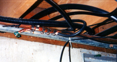 Figure 2. An inadvertent neutral-to-ground connection in an equipment panel caused a ground loop current of more than 1.7 A to flow in KROA’s grounding circuit. This current generated a white background noise in the station’s audio signal.
- A form of halo ground had been constructed inside the transmitter room using lengths of copper water tube to which various pieces of equipment were connected (Figure 3). The innovative halo provided a convenient ground bus, although connections to it could not be made with low-impedance grounding lugs. This factor may have contributed to the station’s sub-optimum signal-to-noise ratio.
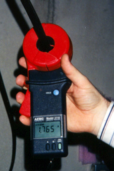
Figure 3. Portion of an interior grounding bus, constructed from copper plumbing tube and installed in station KROA’s transmitter room. Several equipment-ground conductors were con the copper tube with hose clamps (center of photo). High-impedance grounding connections such as these detracted from optimum station signal quality.
- Based on a belief that "too much" grounding was attracting lightning strikes, grounding connections on the tower’s six sets of guy wires had been disconnected sometime in the past (Figure 4). This action may, in fact, have helped direct lightning discharge current down the antenna tower itself, bringing the strike closer to the studio/transmitter building.
- Conroy found that the tower and its grounding conductors were connected to three 10-ft deep grounding electrodes located about 10 feet from the tower in a roughly triangular pattern. In principle, this is a sound practice. However, the electrodes required upgrading to reduce their resistance to levels appropriate to the station’s equipment. Conroy also found that the system’s three solid #6 AWG grounding electrode conductors were connected to the tower base using steel clamps, which had corroded, further increasing the resistance to ground (Figure 5).
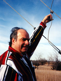 Figure 4. KROA station engineer Wayne Nestor shows disconnected grounding conductors at one of the station antenna tower’s six sets of guy wires. The conductors had been disconnected in the mistaken belief that "too much" grounding caused the tower to attract lightning. The scheme was ineffective, and it may have contributed to one lightning strike’s entering the station’s broadcast studio. New grounding conductors, plus new low-resistance grounding electrodes and a web of 250-kcmil grounding electrode conductors have prevented any subsequent lightning damage to the station and its equipment.
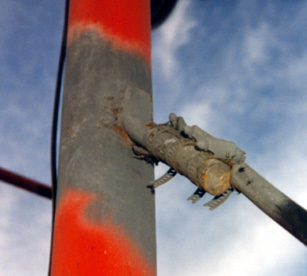 Figure 5. Grounding elecrode conductor connected to the KROA antenna tower using steel clamps. Corrosion, which can be seen staining a layer of gray rust-proofing paint, contributed to resistance levels greater than the maximum values noted in IEEE 142, IEE 1100, TIA/EIA 607 and other recommended practices. These improvised connectors were replaced by corrosion-resistant copper alloy lugs.
Conroy and the station’s engineers concluded that even though the installed system did meet Code requirements, KROA’s equipment—and its signal quality—would benefit from better grounding. The NEC’s grounding requirements are intended to prevent injury to personnel and to avoid fire hazards. They do not take into account the more stringent grounding requirements of sensitive electronic equipment. Conroy believed that recommended practices such as those published in IEEE 142, IEEE 1100 (The Emerald Book) and TIA/EIA 607 would improve the station’s grounding system significantly.
Specifically, recommended practices for grounding sensitive electronic equipment call for ground resistance values to be as low as practical. Fixed limits are not mandated in either IEEE or TIA/EIA publications, but a ground resistance between 1 and 5 ohms has generally been "found to be suitable".
Back to TopWet Soil Doesn't Always Mean Low Resistance
The 30-ohms resistance displayed by KROA’s existing grounding electrodes is interesting in that the water table in the surrounding Platte River basin is only five feet below grade. With such moist soil, one would ordinarily expect low resistivity (and resistance). In this case, however, the combination of water purity and soil composition actually led to a rather high resistivity near the surface.
This situation is not uncommon, according to CPC’s Conroy. "We"ve found that river bottom areas are among the harder places to obtain a good ground," said Conroy.’sand and gravel, even when wet, can be a very poor grounding medium.
"People think moist soil equates to low resistance, but that’s not necessarily true. Then, when the electrician drives a couple of 10-ft rods, they"re misled into thinking they have a good grounding system. Such a system may meet NEC minimums (25 ohms for the primary electrode, unspecified limits when multiple supplementary electrodes are installed), but that doesn"t mean resistance is low enough for sensitive electronic equipment. The radio station is a perfect example. Everything in the building except the light bulbs and the coffee pot could be classified as sensitive electronics, and equipment like that absolutely needs a good, low-resistance ground!"
Back to TopCheap Insurance
Based on Martin Conroy’s recommendations, the station’s management made several improvements to the grounding and lightning protection systems:
-
A high-capacity transient voltage surge suppressor (TVSS) was installed at the main electrical panel, thus providing better protection against voltage spikes from the utility grid. Conroy specified a surge suppressor suitable for the center-tapped delta configuration. He maintains that "A TVSS is about the cheapest lightning insurance you can buy. TVSS devices are available in a broad range of sizes and types, they don"t cost much, and they"re easy to install. But, they require a good grounding system to work properly."
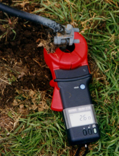 Figure 6. A new 40-ft deep copper-clad grounding electrode installed at station KROA by Computer Power & Consulting indicated a ground resistance of only 2.6 Ohms, well within recommended limits. A copper-alloy clamp connects the electrode with a stranded 250-kcmil grounding conductor. Conductors of this size surround the tower in a ring ground.
 - A 40-ft deep copper-clad grounding electrode was driven near the main service entrance. Heavy gage (250-kcmil) stranded copper grounding conductor was used to connect the electrode with the ground bus linking the transformer and the main electrical panel. All connections were made with corrosion-resistant bronze connectors (Figure 6).
- Three 50-ft grounding electrodes were driven in a triangular pattern surrounding the antenna tower. Ground resistance at all of the deep electrodes consistently measured less than 3 ohms. The electrodes were connected with the tower using special welded grounding taps. Down-conductors from the antennas were rewired in 250-kcmil copper. These were bonded to the electrodes using bronze connectors. All three electrodes were interconnected to form a ring ground surrounding the tower. The ring was then connected to the station’s principal grounding electrode, again using 250-kcmil copper. The entire grounding system now exhibited a uniform and low (less than 3-ohms) ground resistance.
CPC has found that when near-surface ground resistance is high, it is often better to drive one or more deep electrodes than to rely on multiple shallow rods. This practice is not universally applicable, however, and each installation must be designed on the basis of ground resistance measurements taken using properly conducted fall-of-potential tests.1
Back to TopNo More Equipment Damage, Signal Quality Improves
The new ground system works as planned. Despite many lightning strikes and other disruptions, there has been no equipment damage at the station since the system was installed in 1997. One severe voltage surge from a strike to the power grid did destroy the TVSS, but the surge protector did its job, shunting the current safely to ground. The transmitter never felt a thing.
"Our philosophy is that a TVSS should take the damage, not the equipment it protects," said CPC’s Conroy. "But, any TVSS can only work the way it’s supposed to if it is properly grounded. Remember that a TVSS essentially diverts the lightning energy to ground. Without a good ground connection, the strike’s energy could easily bypass the TVSS and find its way inside the structure."
KROA station engineer Wayne Nestor is very satisfied with the new system. "We"ve had essentially no lightning problems at the KROA studio/transmitter since the upgrade. Our antenna tower continues to collect its share of lightning strikes, but all strikes have been confined to the tower and its grounding system. No strikes have side-branched into the studio. Also, despite the many strikes and several years of outdoor exposure, there has been no corrosion and all connections have remained in perfect condition."
Back to TopThe Bottom Line
Antenna towers and the stations they serve are particularly vulnerable to lightning damage. In order to ensure safety and provide adequate protection to expensive broadcast equipment, several important steps should be taken when considering the grounding system for radio and TV transmitters and antennas:
- First and foremost, the entire electrical system must be properly installed according to NEC requirements.
- Equipment and system grounding circuits must be connected to the neutral bus only at the primary electrical panel (first disconnect), from which point a connection must be made directly to the primary grounding electrode. Failure to follow this requirement can result in a safety hazard and can lead to the generation of disruptive ground-loop currents.
- The connection between antenna towers and grounding electrode conductors should be exothermically bonded, welded with copper-base filler wire or made mechanically using corrosion-resistant brass or bronze connectors. Improvised connections using steel straps or hose clamps will not provide lasting protection against corrosion.
- As recommended in §6.4.1.1.4 of IEEE 1100, impedance of the equipment-grounding and neutral conductors between equipment and the neutral-to-ground bond should not exceed 0.25 ohms. Equipment-grounding circuits should contain separate copper ground conductors (green wires), whether or not metallic conduits or cable trays are used to ground equipment cabinets and associated hardware. Copper conductors and connectors, used throughout the system, are the best safeguards against changes in resistance over time, particularly against those changes caused by corrosion.
- It is strongly recommended that the grounding electrode(s) exhibit as low a resistance to earth as possible. IEEE 142 notes that a resistance between 1 and 5 ohms is generally suitable.
- Several grounding electrodes can be installed around the tower in a ring or star pattern, as they were at KROA. In many cases, multiple electrodes can help provide acceptably low ground resistance. Deep electrodes or conductivity-enhancing "chemical" electrodes may be needed if ground resistivity is high. Ring grounds constructed from bare, heavy-gage copper conductors have been found to be particularly effective.
- All connections in the grounding electrode circuit should be exothermically bonded or made with corrosion-resistant copper-base mechanical connectors.
- A TVSS of appropriate capacity should be installed at the service entrance. Supplementary surge protectors can be installed on branch circuits. It is absolutely imperative that all surge suppressors be grounded. An ungrounded TVSS will not protect downstream equipment
The Principals
FM station KROA(95.7 MHz) is owned and operated by Grace University, Omaha, Nebraska. The 100,000-watt station provides religious programming, sacred and classical music and news coverage to large portions of Kansas, Iowa and Nebraska.
 Martin Conroy is president of Computer Power and Consulting Corporation, Omaha, Nebraska. For the past 18 years, CPC has specialized in the field of power quality consulting and technical services, diagnosis and remediation, as well as seminars and technical papers. He is a Nebraska Class A Electrical Contractor and an IAEI-certified Electrical Inspector. CPC operates throughout the USA. The company can be reached at 402-571-2322 or on the Web at: www.cpccorp.com
Footnotes
 "Deep Earth Grounding", a white paper by Martin D. Conroy, is available on CPC Corp's website. The paper examines grounding-test results at 140 sites in the U.S.A.