For years CDA has often been asked if there is a special or specific method required to fabricate satisfactory soldered joints between copper tube and copper alloy flanges. These flanges are often referred to as brass or bronze but for this discussion they will be identified as copper alloy flanges.
All soldered joints should be fabricated using the steps and procedures outlined and defined in the ASTM B828 - Standard Practice for Making Capillary Joints by Soldering of Copper and Copper Alloy Tube and Fittings. Additional information related to soldering of copper and copper alloys can be found in the Copper Tube Handbook, or in Soldering and Brazing Copper Tube and Fittings (Publication A1143), or if the flanges are manufactured from a no-lead copper alloy review the information found in Recommended Practice for Soldering of No-Lead Copper Alloys (Publication A4108).
The most important thing to understand when soldering copper alloy flanges is that they contain a huge heat-sink in the flange face itself. If the flange socket is not at a temperature high enough to allow the solder alloy to remain molten through the entire depth of the fitting socket, insufficient solder fill may occur. To overcome this possibility careful additional heating of the flange face may be necessary to accommodate for the loss of heat by normal thermal conductivity through the flange face.
Recommended Steps for Satisfactory Soldering of Copper Alloy Flanges
NOTE: Steps listed below are for a horizontal joint configuration but would be similar for joints in the vertical position as well.
- Measure tube so it provides for full insertion to the back of the female socket of the flange.
- Cut the tube square (perpendicular) to the run of the tube at the desired length.
- Ream the inside of the tube and and deburr the outside edge if the tube.
- Clean the oxides from the the outside of the tube and the inside of the female socket.
- Apply a thin even coating of an approved solder flux material to the outside of the tube and the inside of the female socket.
- Remove any excess flux that is pushed to the face of the flange when the tube is inserted to the back of the socket.
- Begin preheating the bottom two thirds of the tube (see Figure 1) as described in Publication A1143 under section Heating.
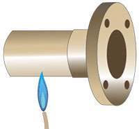 Figure 1: Heating Tube
 - Preheating of the flange fitting socket (see Figure 2) would be as described in Publication A1143 under section Heating.
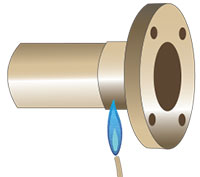 Figure 2: Heating Socket
Because the flange face is such a huge heat-sink and tends to rob heat from the back of the fitting socket, additional heating of the flange face (see Figure 3 & 4) in the area of the tube socket may be necessary to overcome the possibility of reduced heat at the back of the flange socket.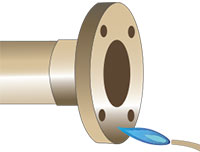 Figure 3: Heating Flange Face at Socket
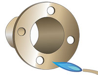 Figure 4: Heating Flange Face
 - Application of solder alloy should be accomplished (see Figure 5) as noted in Publication A1143 under section Applying Solder.
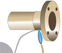 Figure 5: Applying Solder
 - Once the soldered flange joint is completed allow the flange to cool naturally. Shock cooling or "quenching" may cause rapid shrinking of the cast flange that could contribute to cracking of the solder alloy within the soldered joint or the flange itself.