For many years the two most common methods of joining copper tube and fittings have been soldering and brazing. These tried and true methods are in a number of ways similar, yet there are also several distinct differences that set them apart. This paper explains the similarities and highlights the differences between the two joining processes to help determine which joining method is most desirable.
Overview
The most common method of joining copper tube is with the use of a socket-type, copper or copper alloy fitting into which the tube sections are inserted and fastened by means of a filler metal, using either a soldering or brazing process. This type of joint is known as a capillary or lap joint because the socket of the fitting overlaps the tube end and a space is formed between the tube and the fitting. This space is called the capillary space. The surfaces of fitting and tube that overlap to form the joint are known as the faying surfaces. Tube and fitting are then solidly joined using a filler metal that is melted into the capillary space and adheres to these surfaces.
 Figure 1. Lap Joint - Tubular Parts
The filler metal is a metal alloy that has a melting temperature below that of either the tube or fitting. The melting point of copper (Cu) alloy UNS C12200 is 1,981°F/1082°C. As such, the filler metals for soldering and brazing copper and copper alloy tube and fittings must have melting temperatures below this temperature.
The basic difference between soldering and brazing is the temperature necessary to melt the filler metal. That temperature is defined to be 842ºF/450ºC by the American Welding Society (AWS) but is often rounded to 840ºF. If the filler metal melts below 840ºF the process being performed is soldering. Above that temperature, the process is brazing.
Filler Metal Solders
The primary element used in solder filler metals is tin (Sn), because tin has affinity for copper and wants to adhere to the copper alloy tube and fitting. However, the use of pure tin (Sn) would make a very weak joint, and as with any pure metal would be very difficult to work with. Therefore, other elements are added to alloy with the tin to provide strength and make the filler metal easier to use. Prior to 1986, the most common solder filler metal used to join copper alloy tube and fittings was 50/50 solder, which is 50% tin (Sn) and 50% lead (Pb). Because of nationally mandated requirements set forth in the Safe Drinking Water Act, lead bearing solders were prohibited for use in potable drinking water systems. With the prohibition for the use of 50/50 (Sn/Pb) solder, many new and stronger lead-free alloys have been developed and are in common use today for all soldering applications. These consist of alloys that are still primarily tin with the addition of various combinations of other elements, such as nickel, bismuth, antimony, silver and even copper.
Filler Metals: Brazing Alloys
Brazed joints are generally used to achieve higher joint strength or fatigue resistance. To accomplish this, filler metals stronger than those composed primarily of tin must be used. However, this increased strength generally comes from filler metals made of materials that melt at higher temperatures. The brazing temperatures for most of the brazing alloys used to joint copper piping systems (BCuP and BAg alloys see below) are roughly between 1,150°F/621°C and 1,550°F/843°C.
The most commonly used brazing filler metal types, used to join copper tube and fittings fall into two distinct categories:
- BCuP Alloy (pronounced b-cup) - where the B stands for Brazing, Cu is the chemical symbol for Copper, and P is the chemical symbol for Phosphorous. Therefore, a BCuP brazing alloy is primarily a copper-phosphorous brazing alloy that may contain from 0%-30% Silver (Ag).
- BAg Alloy (pronounced bag) - where the B stands for Brazing and Ag is the chemical symbol for Silver. While there are other elements found in BAg alloys besides silver, the majority of BAg alloys may contain silver content of anywhere between 24% and 93%.
Joint Requirements and Strengths
Whether the joining process being utilized is soldering or brazing, there are certain basic steps that should be followed to consistently obtain strong joints. Those basic steps are described in the installation standard (ASTM B828). This standard and its procedures deal with end preparation, cleaning and the proper application of heat and filler metal. They are explained in greater detail in the CDA Copper Tube Handbook.
Whether the joining process being utilized is soldering or brazing, the tube should be fully inserted into the fitting to the back of the fitting cup.
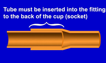 Figure 2. Tube Joint Detail
The depth of overlap or socket depth in a lap type or capillary joint fitting is specified in manufacturing standards ASME/ANSI B16.18 and B16.22 for solder pressure fittings. This is an important dimension because ideally the filler metal should be melted into the capillary space so that it flows completely to the back of the fitting cup and completely bridges (fills) the space between the tube and the fitting. Although 100% penetration and fill of the capillary space fitting is desired, a solder joint fill of 70% fill (or no greater than 30% voids) is considered satisfactory to obtain joints that can withstand the maximum recommended pressures for soldered copper tube and fitting systems.
A major difference between brazed and soldered joints is in the amount of joint overlap or fill necessary to develop full strength of the joint. In a brazed joint, full insertion of the tube to the back of the fitting cup is still highly recommended; however, complete fill of this joint space throughout this entire length is not necessary to achieve full joint strength. According to the American Welding Society (AWS), it is suggested that the brazing filler metal penetrate the capillary space at least three times the thickness of the thinnest component being joined, which is usually the tube. This is known in the industry as the AWS 3-T Rule.
Because of the increased strength of brazing alloys, even this rather small amount of fill penetration will result in a properly fabricated brazed joint stronger than the tube and or fitting themselves. However, unlike a solder joint, where the cap or fillet provides minimal additional strength, a brazed joint should be fabricated so that a well-developed fillet or "cap" of filler metal is provided between the tube and fitting on the face of the fitting. This fillet, or cap as it is often referred to in the trade, permits the stresses developed within the joint (by thermal expansion, pressure or other cyclic reactions such as vibration or thermal fatigue) to be distributed along the face of the fillet. In a brazed joint fabricated without the well-developed concave fillet, all stress would be concentrated at the sharp point of contact between the tube, braze alloy (filler metal), and the fitting, possibly leading to development of a stress fracture in the tube at that point. Creation of the fillet when fabricating the brazed joint greatly minimizes this possibility.
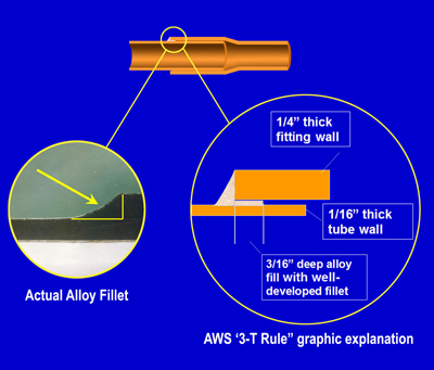 Figure 3. AWS 3-T Rule Explanation
Besides the strength of the filler metal in the joint, the overall strength of the joint or assembly (tube, fitting and joint) following the joining operation must also be considered when choosing whether to use soldered or brazed joints. As discussed, by definition the temperature that defines the difference between soldering and brazing of copper is approximately 840°F/449°C. This temperature is much more important than just an arbitrary definitional threshold. It is important because 700°F/371°C is the temperature at which copper begins to anneal, or be changed from hard temper (rigid) to annealed temper (soft). With this change in temper comes an inherent loss in strength - hard temper copper is stronger than annealed temper copper. The overall amount of annealing that occurs, and thus strength that is lost, is determined by the temperature and the time the material spends at that temperature. The higher the temperature, the less time it takes to change from hard temper to soft temper.
Since brazing temperatures must exceed the melting point of the brazing alloys, between 1,150°F/621°C and 1,550°F/843°C, the process of making a brazed joint causes the base metals to anneal or soften, resulting in a reduction in the overall strength of the assembly. While a brazed joint is demonstrably stronger than a solder joint, the Rated Internal Working Pressure, that is the 24/7 allowable working pressure of the system, is lower for annealed tube (see Copper Tube Handbook, Tables 3a through 3e).
Consequently, this must be taken into account when deciding whether to solder or braze. While brazed joints are stronger, and in general are more resistant to fatigue (vibration, thermal movement, etc.), system working pressures must conform to the allowable limits of annealed tube.
Additional References
- American Welding Society: Soldering Handbook - 3rd Edition
- American Welding Society: Brazing Handbook - 4th Edition
- AWS A5.8/AWS A5.8M: Specification for Filler Metals for Brazing and Braze Welding
- ASTM B32-04: Standard Specification for Solder Metal