Piping
Cu-Ni is used for piping systems in a wide range of sizes. To obtain the high performance achievable from Cu-Ni, particular attention should be given to using alloy compositions which comply to international standards, maintaining flow velocities within accepted limits, avoiding areas of local turbulence and extended exposure to polluted water and ensuring good commissioning/start up practices.
Guidelines For Good Surface Film Formation:
- Clean dirt, lubricants and debris from the system.
- Avoid introduction of solid matter by installation of strainers.
- Use clean, unpolluted seawater or fresh water for hydrotesting. If polluted water has been used, it should be disposed of quickly and the pipework rinsed properly with clean sea water or fresh water. If subsequent long stagnant conditions are expected, blow dry the systems.
- The commissioning of a system with intermittent flow, such as a fire fighting system should be conducted in sea water with low levels of suspended matter e.g water from the open sea. However, the seawater has to be replaced by oxygenated water within 4-5 days to avoid putrefaction.
- Ferrous ions from additions of ferrous sulfate or by installation of simulated iron anodes can improve film formation and help protect against sulfides in waters.
- Mature film formation depends on seawater temperature but can take up to 3 months to achieve. Particular care to avoid extended exposure to sea water polluted with sufides is required during that time.
- A system with continuous pumping activity, such as a cooling system, can be operated under normal design flow conditions. In sea water and water containing high levels of suspended matter, the minimum flow rate should be above 0.5-1m/s (as it depends on pipe diameter as well) to prevent deposits forming. In sea water containing entrained sand the flow rate should be decreased by 1-1.5m/s
Guidelines for Prevention of Erosion Corrosion:
Control Flow rate- The maximum flow rate should not exceed the maximum designed flow rate.
- Applied flow rate depends upon alloy, pipe diameter and specification used, e.g BS MA 18, DIN 85004-2. Typically, these may be:
| Alloy | Typical maximum Flow Velocity, m/s |
|---|---|
| 90-10 Cu-Ni | 3.5 |
| 70-30 Cu-Ni | 4.0 |
| 66-30-2-2 Cu-Ni-Fe-Mn | 6.5 |
- For short duration, flow velocities of 10-15 m/s are acceptable
| Conditions in the system | ||
|---|---|---|
| Duration | Clean seawater or fresh water with-out deposits | Polluted seawater or fresh water where deposits are present |
| 4-6 days | Keep the system filled |
Commissioned system:
|
|
New system:
|
||
| > 4-6 days | Keep the system filled and replace the water by oxygenated water every 2-3 days |
Possibility I:
|
|
Possibility II:
|
||
Guidelines for Chlorination:
Chlorine is added to sea water cooling systems to control fouling. Chlorine is usually generated electrolytically or added in the form of sodium hypochlorite.
The general corrosion rate of copper alloys is not affected much by moderate doses of chlorine at normal flow rates but under turbulent conditions, the safe operating velocity can be reduced if the chlorine dosing is too high.
Recommended levels for residual chlorine content:
- For continuous dosage, 0.3 ppm with a maximum of 1 ppm
- For intermittent dosage, a level of 0.5 ppm
- Simultaneous chlorination and ferrous sulfate treatments are not recommended
Notes:
The effect of chlorine levels on erosion/corrosion has recently been reassessed for piping. Research work sponsored by KME is available.
Also, in more recent times it has become appreciated that galvanic corrosion can be less pronounced for some metal combinations in chlorinated rather than in non-chlorinated seawater systems. Cu-Ni is significantly more galvanically compatible with stainless steels when the system is chlorinated.
Connection Guidelines:
- The mismatch of pipe ends should not exceed the half of wall thickness, however it has to be less than 2 mm
- The preferred maximum depth of excessive weld root penetration depending on pipe diameter ex DIN 85004 is:
| Nominal pipe diameter [mm] | The max. protrusion of the welding root [mm] |
|---|---|
| <40 | 1.5 |
| 50-150 | 2.0 |
| 175-250 | 2.5 |
| >300 | 3.0 |
Guidelines for Correct Piping Design and Installation:
- Streamlining minimises pressure drop, required pumping power and probability of erosion attack
- Run piping as directly as possible
- Consider the effect of r/d-ratio for bends and the effect of sudden enlargement and contractions on the pressure drop . Bend radii r greater or equal to 1.5d or angled branches are preferable.
- Choose square stub-end flanges and cut the gasket flush with the inner surface of the pipe. If rolled-over type flanges are used, the design velocity should be reduced by 0.25-0.5 m/s.
- Cut gaskets flush with the inner pipe diameter
- Control the flow with least number of valves.
- Ensure operators have means to control and measure flow rates.
- Ask the valve manufacturer for data related to the effect of weld geometry on the pressure drop in the system. In most instances there are considerable variations for nominally similar valves.
- Provide a downstream distance 5 x ID from pumps and valves to bends.
Useful References and Links:
- Protection of Seawater System Pipework and Heat Exchanger Tubes in HM Surface Ships and Submarines in Sea water systems; UK Ministry of Defence Standard 02-781 Issue 2- May 2009.
- Living with the Threat of Microbiologically Influenced Corrosion in Submarine Sea Water Systems-the Royal Navy Perspective; by Lt. G.J.E. Nicklin RN, MoD, UK. ©
- British Crown Copyright 2008/MOD 9th International Naval Engineering Conference and Exhibition (INEC 2008) April 2008 Hamburg.
- Copper Nickel Piping for Offshore Platforms, CDA Inc Application Data Sheet 708/5.
- Materials Selection for High Reliability Sea water systems; B.Todd; CDA Inc Seminar Technical Report 7044-1919. The Application of Copper Nickel Alloys in Marine Systems.
- W.Schleich. Typical Failures of CuNi 90/10 Seawater Tubing Systems and How to Avoid Them. Eurocorr 2004 Paper 124.
- British Standard BS MA 18. Salt Water Piping Systems in Ships.
- DIN 85004-2: 1996 Copper Nickel Piping Systems, Part 2: General Guidelines for Construction, Fabrication, Testing.
- Fabrication.
- Heat Exchangers and Piping Systems from Copper Alloys Commissioning, Operating and Shutdown. KME Publication.
- Cu-Ni Seawater Piping Systems. G. Wildsmith. Proceedings of Marine Engineering with Copper Nickel. London April 1988.
- The Design and Installation of 90-10 Sea water Piping Systems. Nickel Development Institute Publication 1107.
- Reference Section/Seawater Piping.
- Application of Copper-Nickel Alloy UNS C70600 for Seawater Service; by W.Schleich; Paper 5222 Corrosion 2005. (©NACE).
Valves and Pumps in Copper Alloy Systems
General
Many corrosion problems in seawater systems occur in valves. Often such problems are due to the use of steel or cast iron valves with non-ferrous piping. Although the life of such valves in a steel or cast iron pipe system is short (i.e., two to three years) when fitted in an alloy system, it may be less than a year due to the galvanic effects from the piping.
The three main components of a valve are the body, valve seats and the shafts or stems; these will be considered separately. It should be noted, however, in a system with a nominal seawater velocity of a few metres-per-second flow through the valve, that the valve, depending on its design, may give rise to turbulence and much higher local velocities, particularly when the valves are used for throttling.
Valve Bodies
The basic low cost valve used in ferrous pipe systems has a cast iron body with 60-40 brass internals. Depending on design, corrosion rates of several millimetres per year can occur on the body. The body cathodically protects the internals (until a layer of graphitic corrosion product forms) and the valve will function for two to three years.
Coatings on valve bodies are often used but their success depends mainly on the valve design (see later). In all cases, the life of the coating depends on its integrity, as manufactured, after installation and in service. Any break in a coating can result in intense corrosion and perforation or the valve body.
Upgrading of valve body materials to give higher reliability requires the use of alloys with good corrosion resistance. Such materials are copper base alloys such as nickel aluminum bronzes, Admiralty and leaded gunmetals and cast Cu-Ni alloys. All these alloys are characterized by good resistance to static seawater (necessary for shut-down conditions) and to flowing seawater. Table 1 gives some data under static and flowing conditions.
| Quiet seawater 0.06 m/s |
Moderate velocity 8.25 m/s |
High velocity tests 35-42 m/s |
|||
|---|---|---|---|---|---|
| Alloy | General corrosion mm/year |
Maximum pitting mm |
Corrosion mm/year |
Corrosion rate mm/year 30 day test |
Remarks on low velocity data |
| 88/10/2 Cu /Sn/ Zn Admiralty Gunmetal | 0.025 | 0.025 | 0.4 - 1.0 | 0.75 - 1.1 | 42 months at Freeport, Texas |
| 85/5/5/5 Cu/Sn/Zn/Pb | 0.018 | 0.030 | 1.0 | 1.3 | " " |
| 10/5/5 Al/Ni/Fe remainder copper | 0.055 | 1.2 | 0.42 | 0.7 - 1.0 | 442 days at LCCT |
| 70-30 Cu Ni + 1.6% Cr | 0.0010 | 0.28 | 0.22* | 0.5 | 181 days at LCCT |
| * At 15.3 m/s | |||||
In relation to Table 1, it is interesting to note that in some cases, the corrosion at about 35-42 m/s is similar to that at 8.25 m/s. This indicates that erosion corrosion which typically might occur at areas of local turbulence such as tight angled bends or downstream of pumps and valves, is occurring at the lower velocity and, under these circumstances, increase in velocity produces little increase in corrosion. The aim should be to use the alloy at a velocity lower than that causing erosion corrosion. Unfortunately, this cannot always be calculated so that where erosion corrosion is a possibility, alloys with high resistance such as nickel aluminum bronze or cast Cu-Ni (plus chromium) should be used.
Ni-Resist iron valves are often used in ferrous systems to improve the valve reliability. They are also used in non-ferrous systems but copper-alloy valves are more common in such systems. Nickel aluminum bronze has high strength and this makes it attractive, particularly for large valves. Also, it has high resistance to impingement attack and this may be of importance in globe valves used under throttling conditions.
Valve Seats and Stems - Non-Ferrous Systems
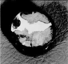
Valve seats, particularly those in throttling service, experience high water velocities, and materials with high resistance to fast flowing seawater such as stainless steels, nickel-base alloys and Ni-Cu alloy 400 are required. Experience shows that when manufacturers upgrade the body material they often use the same materials for seats and stem as in a cast iron valve, i.e., 60-40 brass. Under these conditions the life of the valve internals is extremely short because, having lost the cathodic protection of the ferrous body, they fail by dezincification in a few months. Figure 1 shows dezincification of a 60-40 brass stem from a bronze valve. This is probably the most common cause of failure in non-ferrous valves. Although this type of corrosion is well-known, the rate of attack is often surprisingly high. The sample in Figure 1 failed in less than one year the original diameter was 25 mm.
Although stainless steel (AISI Type 316) will give good life in a non-ferrous valve, it is liable to pit (particularly in crevices) when the system is not in use and on a life cycle cost basis, the nickel-copper alloys are a better choice.
In ball and butterfly valves, one of the seats may be non-metallic, e.g., an elastomer.
Ni-Cr-Mo-Nb alloy 625 which has high resistance to both static and flowing seawater has been used as a weld overlay to produce highly resistant surfaces in critical areas of valves. This alloy has excellent weld deposition characteristics and can be used as a general purpose overlay for avoidance of, or repair to, areas of corrosion damage in carbon, low alloy and stainless steel components.
Effect of Valve Design on Materials Selection
Valves are a relatively expensive part of a seawater system but the cost of a valve depends on the design used. Figure 2 shows some commonly used valve designs and gives an indication of their weight and pressure loss. Apart from any manufacturing difficulties, it is evident that a globe valve will be much more expensive than a butterfly valve because of its much greater weight. It will usually be more satisfactory to select reliable materials for valves, such as a butterfly valve, rather than to use an expensive design of valve, for example, a globe valve and try to economize on materials. Where the use of a globe valve is desirable, for example, for its good flow control characteristics, then the extra cost of corrosion resistant materials appropriate to the design must be accepted.
Some designers attempt to avoid corrosion problems by lining the valve. This is also related to the valve design; for example, butterfly valves are a simple shape and the body can be provided with a thick rubber lining which can be clamped firmly between the flanges joining the valve to the pipes and is not dependent on perfect adhesion between the rubber and the body. A gate or globe valve, however, is of complex shape and a lining, to be successful, must adhere perfectly to the metal surface. Experience shows that such adhesion is difficult to achieve and linings in valves of this type often have a short life.
A rubber-lined butterfly valve has certain features which must be considered in order to avoid corrosion problems. For example, the shafts, on which the butterfly turns, penetrate the lining and it is necessary to provide a positive seal between the lining and the stem to prevent access of seawater to the cast iron body. Failure to do this has resulted in valves failing due to corrosion products building up behind the lining causing seizure of the butterfly and stem.
Another commonly used seawater system valve is the membrane valve. This consists of a flexible membrane usually of rubber which separates the valve internals form contact with seawater. When operated, the membrane is extended into the stream restricting or shutting off flow. The shape is again simple and rubber linings on the body are effective. Cavitation damage to the rubber membrane can occur with severe throttling.
It is interesting to note the complex flow path within a globe valve. Several sharp changes of direction occur inside the valve and this gives rise to severe turbulence which can cause impingement corrosion on the valve body. Materials of high impingement resistance, such as nickel aluminum bronze or cast 70-30 Cu-Ni, are recommended when this type of valve is chosen.
Table 2 provides a summary of materials suitable for seawater valves in non-ferrous systems.
| Type of valve | Body material | Ball, disc, or seat material | Stem material |
|---|---|---|---|
| Butterfly valves | Gunmetals 5% nickel aluminium bronze Rubber-lined cast iron (provided a seal is fitted at the stem) Cast 70-30 Cu-Ni |
5% nickel aluminium bronze Cast 70/30 Cu-Ni Cast Monel alloy Stainless steel (Type 316) |
Ni-Cu alloys 400 or K500 Stainless steel (type 316) 5% nickel aluminium bronze |
| Globe, gate, or ball valves | As above, except that rubber lined valves should be avoided | As above | As above |
| Membrane valves | Rubber lined cast iron | Rubber (membrane) | Not critical as there is no seawater content |
Galvanic Considerations in Valves
Copper-base alloys have similar potentials and can be used together without fear of serious galvanic effects. Where carbon steel or cast iron bodies have been fitted with brass trim, these will have received considerable galvanic protection from the large area of ferrous material and may give a useful life. Upgrading the body material to copper-base alloys will, by removing the cathodic protection effect, give rise to corrosion of the trim. It is good practice to arrange for the trim material to be cathodic to the body, hence the use of alloys such as Ni-Cu alloys 400 and K-500 and stainless steels. The use of copper-alloy valves is desirable in copper-alloy pipe systems so as to retain galvanic compatibility. The use of unprotected ferrous valves in non-ferrous systems should be avoided.
(The section on valves has been adapted from Materials Selection for High Reliability Sea water systems; B.Todd; CDA Inc Seminar Technical Report 7044-1919. The Application of Copper Nickel Alloys in Marine Systems).
Seawater Pumps
Centrifugal pumps are normally used in seawater systems and are often driven by constant speed electric motors. At the normal speed of rotation, the tip speed of the pump impeller can reach 20 m/s and at this velocity, most copper alloys corrode rapidly in seawater. Fortunately, however, only certain components of the pump are exposed to these high velocities, and apart from these components, copper-base alloys can usually be used successfully in copper alloy systems.
Pump Casings
In copper alloy pumps, there is normally sufficient clearance left between the impeller and the casing so that the water flowing from the impeller does not impinge directly on the casing but is absorbed into the slower moving stream of water flowing over the metal surface towards the pump delivery pipe. Provided direct impingement is avoided, materials such as gunmetals, aluminum bronze and cast 70-30 Cu-Ni alloy perform satisfactorily. However, there have been cases of premature pump casing failures in recent years showing that direct impingement can occur. This may be due to increase in pump speed or the tendency to uprate the output from standard pump designs. Where such failures have been experienced, the life of the casing has been very short, for example, about 18 months. To avoid failures of this type, either the design must be amended so as to reduce seawater velocity at the metal surface, or materials of higher resistance must be used. Experience shows that cast 70-30 Cu-Ni and 5% nickel aluminum bronze have higher resistance than gun metal or tin bronzes. Recent research, however, has shown chromium-containing 70-30 Cu-Ni to have higher resistance than other copper-base alloys to fast flowing seawater.
Where pump parts are fabricated by welding from nickel aluminum bronze plate, there is a serious risk of selective phase corrosion (dealuminification) in the heat affected zone of the weld unless remedied by heat treatment. This non-heat treated heat affected zone may crack if stressed, e.g., by water hammer effects.
Pump Impellers
The pump impeller is in contact with fast flowing, highly turbulent seawater and, for circulating pumps which are in use for most of the time, they should be made from a material with high resistance to these conditions. Table 3 provides corrosion data in high velocity seawater for several pump materials.
It is clear from Table 3 that the use of cast iron or mild steel can only be contemplated in pumps operated occasionally. From data in Table 3, Ni-Cu alloys 400 and K-500 and stainless steel Type 316 have very high resistance to flowing seawater, and cast versions of these alloys are preferred for pump impellers.
| Alloy | Corrosion rate | Seawater Velocity |
|---|---|---|
| mm/yr | m/s | |
| Grey cast Iron | 13 | 38 |
| Carbon steel | 9.5 | 40 |
| Ni-Cu Alloy 400 | 0.010 | 43 |
| Ni-Cu alloy K-500 | 0.010 | 43 |
| Stainless steel 316 | 0.005 | 43 |
| Gun metal (85/5/5/5) | 1.30 | 40 |
| Nickel Aluminium Bronze | 0.80 | 38-42 |
These alloys do not suffer from impingement attack but may pit when the pump is stationary and full of seawater. It should be noted, however, that the pitting likely to be experienced is often less severe than the general impingement corrosion which may occur at the tip of a copper-base alloy impeller and hence stainless steel or cast Ni-Cu Alloy 400 are preferred for this application.
(Adapted from Materials Selection for High Reliability Sea water systems; B.Todd; CDA Inc Seminar Technical Report 7044-1919. The Application of Copper Nickel Alloys in Marine Systems).
Fittings
The increasing use of 90-10 copper-nickel in shipbuilding during the 1960s, and particularly in the field of naval ship construction, was accompanied by increasing demand for a multiplicity of fittings and joining methods. A selection of these methods and fittings is presented here.
Contents
Fittings
Fittings differ from one another particularly with regard to their shape and purpose. The main shapes are:
Bend: change in direction of the flowing medium
T-piece: distribution or union of the medium into/from several directions
Reducer: regulation of the flow speed of the medium
Bends
Bends are differentiated by their individual bending radius. Bending radius is measured as a function of the outside pipe diameter, D. Standardised bending radii refer to the inside bend radii and are 1.0xD, 1.5xD, 2.5xD, 5.0xD and 10.0xD. It is to be observed that the bending radius is not equal to the calculated value from, e.g., 1.5 x pipe outer diameter, but is merely an approximate value. The individual exact bending radii are specified in the relevant dimension standards.
Bending radii to a minimum 2.5xD can be formed on conventional bending machines as a pipe bend. Smaller bending radii must be pressed into pipe bends on specially designed presses to accommodate the bulk metal flow. The flow behaviour and the pressing properties depend decisively on the bending radii and the bending angles. The following table shows the various resistance coefficients ζ for pipe bends.
| Bend Radius | Bend Angle | ||||
|---|---|---|---|---|---|
| 15° | 30° | 45° | 60° | 90° | |
| 1.0xD | 0.03 | 0.045 | 0.14 | 0.19 | 0.21 |
| 1.5xD | 0.03 | 0.045 | 0.11 | 0.14 | 0.17 |
| 2.5xD | 0.03 | 0.045 | 0.09 | 0.11 | 0.14 |
| 5.0xD | 0.03 | 0.045 | 0.08 | 0.09 | 0.10 |
| 10.0xD | 0.03 | 0.045 | 0.07 | 0.07 | 0.11 |
T-Pieces
T-pieces are differentiated by their radius in the branch-off. There are 3 types of T-pieces.
- Pressed T-piece
- Pulled T-piece
- T-piece made with a pipe and a saddle.
Pressed T-Piece
Pressed T-pieces (Figure 3) have a radius in the branch-off whose ratio (R) to the outer pipe diameter (D) of the branch-off is >0.2. There is no weld seam in the T-piece and the radius is large. For this reason, the flow conditions in these T-pieces are very good. Normally, pressed T-pieces are manufactured up to a pipe outer diameter of 219 mm.
Pulled T-Piece
Pulled T-pieces have a radius in the branch-off whose ratio (R) to the outer pipe diameter (D) of the branch-off is <0.2. Normally, pulled T-piece fittings are manufactured from pipe outer diameters of greater than 267mm. They produce unfavourable flow conditions as a result of the narrow bending radius. Fortunately, the flow conditions only play a minor role where these large dimensions are concerned. Nevertheless, this should be taken into consideration where critical flow conditions are involved. In contrast to the saddle type, pulled T-pieces are substantially cheaper.
T-piece manufactured with saddle
T-pieces made with a saddle have a radius(R) in the branch-off that has a ratio to the pipe outside diameter (D) of the branch-off which is <0.3. T-pieces with a saddle are normally manufactured from pipe with outside diameters of 267mm or more and involve a welding process. Based on the large radius in the branch-off, these T-pieces have very good flow conditions. However, their manufacture is also substantially more expensive than the necked fittings.
Reducers
The difference between using a reducer for reducing or expanding the flow medium is only a question of function direction and not of design. Investigations have shown that the flow as the diameter reduces is more likely to cause turbulence than the flow when the diameter expands. Figure 6 shows the flow in a reducing situation on the left side and flow in expansion towards the right. The maximum taper angle a for non turbulent flow is calculated as follows1:
α = 2φ<40°
α - Taper angle
φ - reduction / expansion angle
The figures below show the flow conditions during expansion. According to the references, turbulence occurs for expansion angles of φ<2,5° to φ<6° depending on the temperature, diameter and flow velocity.
In practice, turbulence seldom induces damage. That is why reducers in accordance with DIN, EEMUA or ANSI are applied with an expansion angle up to 19°.
Joining methods
A requirement for a multiplicity of joining methods is due to the wide range of conditions on ships, in chemical plants and on offshore platforms. The most commonly adopted methods, with their advantages and disadvantages, are listed here.
The joining methods of 90-10 copper-nickel include the following:
- Welded joints
- Brazed joints
- Flange connections
- Threaded unions
- Press joints
- Connections with pipe couplings
Welded joints are applied to join two components in a permanent manner by means of melting the material or adding a molten weld consumable. The joining method most frequently used for piping systems is a butt weld joint.

Advantages:
- Strength and stability of the union is similar to that of the basic material
- No additional space requirement
- No procurement costs necessary for connecting auxiliary components such as flanges
Disadvantages:
- Cannot be disconnected
- Long assembly times
- Joining of different materials can be problematic
- Possibility of galvanic insulation is poor
- Assembly in fire-hazardous areas not possible without work-intensive and sophisticated fire protection measures
For more detailed information on welding, see Welding and Fabrication Section.
Brazed joints
Brazed joints are applied in order to join two components in a permanent manner. However, the materials are not joined by means of a weld metal process but are adhesively joined together by capillary action of an additional material and heat.
Advantages:
- Low assembly times for small diameters up to RA 38
- Little space requirement
- High pressure stress capacity
- More versatile in joining different types of material
Disadvantages:
- High procurement costs
- Cannot be disconnected
- Possible problems with obtaining sealed joints from outside diameters greater than 76mm
- Sizes of pipe greater than 76mm outside diameter are expensive to process
- No possibility for X-raying the joint for inspection purposes
- Only overlapped joints possible
- Possibility of galvanic insulation is poor
- Auxiliary fittings (sockets) are necessary for joining
- Assembly in fire-hazardous areas not possible without work-intensive and sophisticated fire protection measures
For more information on brazing copper-nickels, see Welding and Fabrication Section.
Flange connections
Flange connections are applied in order to join two pipes together in a manner whereby they can be subsequently disconnected. Types of flanges are:
- Solid flanges
- Weld-neck collars with loose flanges
Advantages:
- Can be disconnected
- Can also be used for large diameters
- Possibility for connecting various types of materials is good
- Possibility of galvanic insulation is good
- Assembly in fire-hazardous areas is possible without work-intensive and sophisticated fire protection measures
Disadvantages:
- Flanges and/or weld neck collars must be welded to the pipe
- Large space requirement
- High procurement costs and assembly times
- Connecting auxiliary flange fittings are necessary
Solid flanges
Solid flanges are manufactured completely from 90-10 copper-nickel. They are used mainly in tanks and vessels where there is an aggressive medium outside the pipes, and in moist atmospheres.
Advantages:
- Corrosive medium can also be on the outside.
Disadvantages:
- Expensive
- Flange must be in a fixed-position with the bolt-hole circles exactly lined up.
- No subsequent turning of the flange is possible.
Weld-neck stub ends with a loose flange
Weld-neck stub ends with a loose flange consist of a weld-neck stub end made from 90-10 copper-nickel and a loose flange made from steel. They are used mainly in areas where only the medium within the pipe line is corrosive and the outer atmosphere is dry.
Advantages:
- Cheap
- Flange can be turned
Disadvantage:
- Susceptible to corrosion in a moist outer atmosphere
Threaded unions
Threaded unions are applied in order to join two components together in a manner such that they can be disconnected again. Threaded unions can be joined into a pipe line by means of welding, brazing/soldering, pressing or clamping.
Advantages:
- Short assembly times
- Joint can be disconnected
- Assembly in fire-hazardous areas is possible without work-intensive and sophisticated fire protection measures
- No inspection such as X-ray or ultrasonic testing necessary
- Possibility for joining different types of materials is good
Disadvantages:
- High procurement costs
- Major space requirement
- Application only up to 76mm outer pipe diameter possible
- Possibility for galvanic insulation is poor
- Joining auxiliary fittings threaded unions fittings necessary
Threaded unions are subdivided according to the sealing mode into the following categories:
- Metallic sealing effect
- Soft sealing effect
Metallic sealing effect
Metallic seals are applied preferably for high temperatures and aggressive media. The metallically sealing threaded unions are differentiated as follows:
- 24°/25° sealing taper
- Cone-shaped sealing
- Sealing with a wedge ring
- Sealing with a cutting ring
- Sealing by means of collar
Soft sealing effect
Soft sealing threaded unions are easy to process. In contrast to metallically sealed threaded unions, no high demands are made on the sealing surfaces. The sealing effect is obtained with an O-ring:
Press joints
Press joints are applied in order to permanently join two pipe sections together. The joint is made by mechanically crimping a special fitting containing an o-ring onto the pipes.
Advantages:
- Short assembly times
- Assembly in fire-hazardous areas is possible without work-intensive and sophisticated fire protection measures
- No inspection such as X-ray or ultrasonic testing necessary
Disadvantages:
- Additional procurement costs for the special fittings
- Require specialised tool for pressing the metal to form the seal
- Low pressure stress capacity
- Cannot be disconnected
- Application possible only up to 108mm outer pipe diameter
- Possibility for galvanic insulation is poor
- Joining possibility for various types of materials is poor
Joining with pipe coupling
Joints with the use of a pipe coupling are applied in order to join two pipe sections together in a manner that can be disconnected. The joint is made by clamping the pipe with a joining device. The couplings are normally in stainless steel with an inner rubber seal which completely galvanically insulates the coupling from the copper-nickel pipe.
Advantages:
- Short assembly times
- Little space requirement
- Assembly in fire-hazardous areas is possible without work-intensive and sophisticated fire protection measures
- No inspection such as X-ray or ultrasonic testing necessary
- Possibility for galvanic insulation is good
- Possibility for joining different types of materials is good
Disadvantages:
- High procurement costs
- Low pressure stress capacity
- Joining sockets are necessary
Standards
Offshore
EEMUA 145 90/10 Copper Nickel Alloy Piping for Offshore Applications Specification: Flanges Composite,PN designed and Solid
EEMUA 146 90/10 Copper Nickel Alloy Piping for Offshore Applications Specification: Fittings
Shipbuilding
DIN 86037 Loose flanges and welding necks for pipes of copper-nickel-alloys
DIN 86087 Fittings for butt welding into copper-nickel-alloy pipelines - Saddle type connections
DIN 86088 Fittings for butt welding into copper-nickel-alloy pipelines - Tees
DIN 86089 Fittings for butt welding into copper-nickel-alloy pipelines - Concentric reducers
DIN 86090 Fittings for butt welding into copper-nickel-alloy pipelines - Elbows
Other Applications
EN1092-3 Flanges and their joints-Circular flanges for pipes, valves, fittings and accessories
Part 3: Copper alloy and composite flanges, PN designed
Typical Mechanical Properties of Fittings
| Rm min. | Rp 0.2% min. | A5 min. | Hardness | |
|---|---|---|---|---|
| Elbows, T-Pieces, Saddles, Reducers in acc. to DIN 86086 | 300N/mm2 | - | 15% | - |
| Elbows, T-Pieces, Saddles, Reducers in acc. to EEMUA 146 | 280N/mm2 | 105N/mm2 | 30% | max. 120 HV5 |
| Weld Neck Stub Ends to DIN 86028 | 280N/mm2 | 100N/mm2 | 15% | min. 70 HB 2.5/62.5 |
| Weld Neck Stub Ends to EEMUA 145 | 280N/mm2 | 105N/mm2 | 30% | max. 120 HV5 |
References
![]() 1. Oertel, Herbert. Prandtl-Fhrer durch die Strmungslehre 11.Aufl. Vieweg-Verlag: Wesbaden 2002.
1. Oertel, Herbert. Prandtl-Fhrer durch die Strmungslehre 11.Aufl. Vieweg-Verlag: Wesbaden 2002.
![]() 2. Eck, Bruno: Technische Strmungslehre. Band 2: Anwendungen. 8. Auflage. Springer Verlag: Berlin, Heidelberg, New York 1981.
2. Eck, Bruno: Technische Strmungslehre. Band 2: Anwendungen. 8. Auflage. Springer Verlag: Berlin, Heidelberg, New York 1981.
Water Hammer
"Water Hammer" is a phenomenon1 resulting from the generation of a pressure shock wave in a fluid caused by a sudden change in flow velocity (e.g. by sudden valve closure or pump shut down) in a piping system. The pressure in the piping suddenly increases, and a pressure wave travels back and forth in the closed-off portion of the system, producing a noise as well as impact loading on the pipe walls and connecting equipment. The velocity of the traveling wave is determined by the compressibility of the fluid and the elasticity of the pipe.
The most violent type of water hammer is due to water column separation1. This can be explained using the example of a pump which is installed up stream of a long lift riser with a horizontal piping portion connected at the top. If the pump is suddenly turned off during pumping up, the internal pressure in the pipes will begin to fall producing a sudden pressure reduction in the horizontal piping. Should, at this time, the minimum pressure be less than the evaporation pressure at the water temperature, the water column separates by a zone of vapour for a short time. As a result, the water concentrates toward the low-pressure section, and the impact causes fierce water hammer.
Premature failures of valves, joints, loosening of supports or even bursting of the pipe are the possible consequences. 90-10 Cu-Ni is frequently applied in fire fighting systems and works considerably well under conditions promoting water hammer. However, examples of good practice1 to prevent water hammer and water column separation follow:
- Install a flywheel on the pump so that, in the event of power outage, it keeps turning by inertia and does not suddenly stop.
- Couple a dashpot to the check valve to give the valve resistance and lengthen its closure time if water flows in the reverse direction in the pipes.
- Install an air chamber to absorb the impact pressure.
- Install an automatic pressure control valve or surge tank to prevent an increase in pressure in the pipe line.
- Keep the water speed in the pipes to a minimum.
- If the horizontal section of a lift riser is long, avoid water column separation by placing its horizontal section at as low an elevation as possible.
- In an underwater pump or a pump in a closed circuit pipeline network, make all the water flow backwards by omitting any check valves.
1Note: Descriptions of water hammer and good practices have been summarised from Piping Manual for Stainless Steel Pipes for Buildings, Nickel Institute Publication Nr. 12008.
Galvanic Considerations
Corrosion is a complex area to understand and mechanisms can interact to alter local or even general material degradation rates. It is often necessary to use a number of different alloys to construct a sea water system and in order to ensure anticipated lives of the components are achieved, the galvanic compatibility of the materials used must be considered. Galvanic corrosion is the enhanced corrosion which occurs to the least noble metal within a mixed metal system, in electrical contact with the other metals and exposed to an electrolyte. To predict which of the metals in contact is the least noble and whether higher corrosion rates may occur than might otherwise be expected, a Galvanic Series for sea water can be used.
Galvanic Series
Alloys nearer the top of the Galvanic Series as shown in this chart are less noble than those towards the bottom. It is seen that copper base alloys are in the middle of the Series whereas steel, zinc or aluminium are appreciably less noble and would be expected to corrode preferentially when coupled to them in a system. Passive stainless steels, highly alloyed nickel alloys, titanium and graphite are all more noble than copper alloys and the copper alloys would therefore risk galvanic corrosion. The further apart the metals are in the Series, the greater the risk of corrosion.
The relative surface areas of the galvanically coupled metals exposed to the sea water have an important influence on the extent of corrosion. The surface area of the more noble alloy normally limits the galvanic current. Therefore, a small area of the more noble alloy in contact with a large area of a less noble alloy can have little effect on the overall corrosion rate of the less noble material. Alternatively, if the relative area of the more noble area is high, then excessively high corrosion rates of the less noble alloy might be experienced.
In general, the copper base alloys have similar nobility and are all galvanically compatible with each other in seawater unless the surface area of the more noble alloy is significantly greater than the less noble alloy. The Cu-Ni alloys are slightly more noble than the nickel-free copper base alloys, but the differences in corrosion potential rarely lead to serious galvanic effects. 90-10 Cu-Ni is slightly less noble than 70-30 Cu-Ni and both are less noble than nickel aluminium bronze but more noble than manganese bronze. Nickel aluminium bronze is therefore preferred as a propeller material for a Cu-Ni hulled boat as the unfavourable area ratio would lead to accelerated corrosion of manganese bronze.
In more recent times it has become appreciated that galvanic corrosion can be less pronounced for some metal combinations in chlorinated rather than in non-chlorinated seawater systems. Cu-Ni is significantly more galvanically compatible with stainless steels when the system is chlorinated.
Problems with galvanic corrosion can usually be avoided by following the rules below:
- use materials situated close together in the galvanic series
- where this is not possible make the key component of a more noble material
- ensure that the less noble material is present in a much larger area than the more noble material
- paint the more noble material. This can be beneficial as it reduces the exposed area of the more noble material even when the paint film is incomplete. An imperfect coating, if the less noble alloy alone was painted, would lead to intensified attack at breaks in the paint film.
- insulate to prevent metal-to-metal contact and thus break the galvanic current e.g. using non-conducting sleeves and gaskets.
Of additional importance to the behaviour of Cu-Ni alloys is that galvanic coupling to less noble alloys, or the use of cathodic protection, can inhibit their biofouling resistance. This is thought to be due to the resultant restricted copper ion release from the surface film.
Pressure Systems
Copper-nickel is widely used in high pressure systems operating at over 105 bar (~1500 psi) and especially where there is an additional need for corrosion resistance or low temperature capability. The ease of forming of the alloys into complex fittings and coils have ensured their continued selection.
Cryogenic systems are a particular type of pressure system and operate at very low temperatures (below about −150 °C, −238 °F or 123 K). Historically, these conditions have applied to research and medical applications but with the development in industrial processes and gas welding techniques, these have become more important to a wider market. Recent investments in large Liquefied Natural Gas (LNG) infrastructures and their associated cryogenic and gas transport systems have further exploited these alloys in critical applications.
The following is provided as general guidance only. International Standards and professional advice should be sought for specific designs.
For safe pressurized systems, it is important to assure structural integrity, regulate pressure and flow and provide pressure relief.
In general the design of pressure systems is based on Maximum Allowable Working Pressure [MAWP] which for a manned, ductile system has a design safety factor typically of 4 or higher. This means that the theoretical burst pressure should be at least 4x MAWP. To be effective, pressure relief devices must not be higher than the Maximum Allowable Working Pressure for the system.
The Maximum Operating Pressure (MOP) is the highest pressure any system may be operated at and typically should be 10-20% below the MAWP to allow for any deviation in actuation of pressure relief devices.
Testing pressures used to assure system integrity for high pressure systems are normally 125-200% of the MAWP. The value used depends on environmental factors such as corrosion, fatigue and temperature, etc. Thus, for pressure systems involving inert, low hazard substances, hydrostatic testing using an inert fluid to at least 1.5 x MAWP or pneumatically [ pneumatic test is usually under water at low pressures - 5 psi - to locate leaks and is mainly used on heat exchanger tube as it is very searching] to at least 1.25 x MAWP are typical. However, for pressure systems involving reactive, high hazard substances, hydrostatic testing using an inert fluid or gas would more normally be to at least 2 x MAWP.
TP ![]() 1.25 to 2.0 x MAWP
1.25 to 2.0 x MAWP ![]() 1.1 to 1.2 x MOP
1.1 to 1.2 x MOP
The British Standard, BS 2871: applicable to non-ferrous seamless tube products does not specify safe working pressures and this is usually a protocol defined by the system design engineer or the organization having design authority. It does however provide calculations that can be used to ascertain the recommended test pressure for many alloy/size combinations. From this standard the Barlow formula can be adapted:
TP=Kt/D
max TP in BS2871 Pt 2 & 3 is 4 kpsi; even if higher pressures are specified elsewhere
Where TP = hydrostatic test pressure(bar), t = actual wall thickness(mm), D =actual outside diameter(mm), K= a material constant:-
| Alloy | Condition | K | UTS [bar] | Note |
|---|---|---|---|---|
| CuDHP | O | 800 | 2200 | These figures are typical only and should not be used without verification. BS 2871 indicates a normal maximum |
| H | 1100 | 3850 | ||
| CuZn30As | O | 1100 | 3100 | |
| TA | 1100 | - | ||
| H | - | 4650 | ||
| CuZn20Al2 | TA | 1250 | 3600 | |
| CuNi10Fe1Mn | O | 1250 | 3200 | |
| H | - | 5400 | ||
| CuNi30Mn1Fe | O | 1600 | 4000 | |
| H | - | 6400 |
Example:
CuNi10Fe1Mn in typical annealed [O] condition,
| Pipe size 38mmOD x 2mm | TP = [1250 x 2]/38 | TP = 65.8 bar |
| [1 bar= 14.5 psi | TP = approx. 954 psi] |
| so, assuming | MAWP = 1.5 x TP | |
| MAWP = 1.5 x 66 bar [rounded up] | MAWP = 99 bar = 1435 psi | |
| and | MOP = MAWP/1.2 = 82.5 bar |
Approximate Burst Pressure can be calculated using Barlows Formula: BP [bar] = [2 x t x UTS]/D where t = actual wall thickness [in mm], D = actual outside diameter [mm] and UTS is the alloy's tensile strength in bar.
1 MPa=10 bar
1 bar= 14.5 psi
1 in= 25.4mm
1N/mm2=1MPa
Useful References:
Enhanced Heat Transfer
Virtually every heat exchanger is a candidate for enhanced heat transfer. Tubes are the basic component of the heat exchanger, providing the heat transfer surface between one fluid flowing inside the tube and other fluid flowing across the outside of the tubes. Tubes are commonly made of copper or Cu-Ni. Depending on the application, the tubes may have extended or enhanced surface on the outside or tubes could be doubly enhanced, that is, with enhancement both inside and outside. Extended surfaces, finned tubes, provide two to ten times as much heat transfer area on the outside as the corresponding bare tube, and this area ratio helps to offset a lower outside heat transfer coefficient.
There are at least two main reasons for using enhanced surface tubes:
1. Size reduction: By increasing tube heat transfer efficiency, the heat exchanger length will be reduced resulting in reduced cost.
2. Improved Heat Transfer: By taking advantage of increased heat transfer surface, heat exchanger capacity and efficiency will be increased
Enhanced tubes are designed for variety of applications. Surfaces are optimized for evaporation, condensation, and liquid to liquid heat exchanger application using different refrigerants and working fluids.
Tubes have been designed for condensing applications with fluids on the inside of the tube, like seawater, that tend to cause fouling. Condensers with a fouling liquid on the inside will have a drop off in performance over time due to fouling. Some designs of tube have been engineered to extend the performance of a unit when tube-side fouling is a problem. The inside tube enhancement increases the internal surface area, improving heat transfer and also will cause turbulence of the tube-side fluid and thus help reduce tube-side fouling.
Useful links for Heat Transfer and Enhanced Surfaces:
Links to Design Standards
- British Standard BS MA 18. Salt Water Piping Systems in Ships
- EEMUA
EEMUA Specifications covering 90-10 Cu-Ni Piping for Offshore Applications are :-
Tubes Seamless and Welded Publication 144
Flanges Composite and Solid Publication 145
Fittings Publication 146
(EEMUA is the Engineering Equipment and Materials Users Association, UK) - ASTM
- ASME
- DIN
DIN Specifications covering 90-10 Cu-Ni Piping for Offshore Applications are:
DIN 85004-2: Pipelines of copper-nickel-alloys-Part 2: Basic principles for design and fabrication, test
DIN 85004-4: Pipelines made of copper-nickel-alloys-Part 4: Technical specifications for tubes
DIN 85004-9: Pipelines of copper-nickel-alloys-Part 9: General principles for the radiographic examination
DIN 86003-1: Ships and marine technology-Design, production and test of pipeline systems for liquid media-Part 1: Design
DIN 86018: Welded tubes made of CuNi10Fe1,6Mn for pipelines-dimensions
DIN 86019: Seamless tubes made of CuNi10Fe1,6Mn for pipelines-dimensions
DIN 86028: Welding necks of CuNi10Fe1,6Mn-Technical specifications
DIN 86037: Loose Flanges and welding necks for pipes of copper-nickel-alloys
DIN 86086: Fitting for butt welding into copper-nickel-alloy pipelines-Technical specifications
DIN 86087: Fitting for butt welding into copper-nickel-alloy pipelines-Saddle type connections
DIN 86088: Fitting for butt welding into copper-nickel-alloy pipelines-Tees
DIN 86089: Fitting for butt welding into copper-nickel-alloy pipelines-Concentric reducers
DIN 86090: Fitting for butt welding into copper-nickel-alloy pipelines-Elbows