- Introduction
- Corrosion Considerations
- Materials Selection in Seawater Systems
- Interactions within the System
- Conclusion
- Appendix
- References
Introduction
Seawater systems are used by many industries such as shipping, offshore oil and gas production, power plants and coastal industrial plants. The main use of seawater is for cooling purposes but it is also used for fire-fighting, oil field water injection and for desalination plants.
The corrosion problems in these systems have been well studied over many years, but despite published information (1) on materials behavior in seawater, failures still occur.
Economic factors have to be considered in selecting materials for these systems and in this context, essentially two types of system can be considered, as follows:
- A low initial cost system largely based on carbon steel and cast iron which will require considerable maintenance over the life of the plant. Such a system is a reasonable choice in areas where labor costs are low and material is readily available.
- A system based mainly on alloy materials which, if correctly designed and fabricated, will require minimum maintenance and will function reliably. Rising labor costs in most industries, together with the need for high reliability in capital intensive plant has produced a trend to this type of system.
In practice many systems are a mixture of these two logical approaches resulting in the high initial costs of one and the high maintenance costs of the other. For example, a plant which has experienced costly replacement to galvanized steel piping may replace it with copper alloy piping leaving valves fittings, etc., in carbon steel and cast iron. The resulting galvanic corrosion effects result in reduced life for these parts. Thus, higher initial costs have resulted in reduced reliability and high maintenance costs.
It is essential therefore in selecting materials for seawater systems to treat the system as a whole. This should include the heat exchangers where these are part of the system. However, this paper is confined to the seawater systems.
Another source of problems is the different requirements of plant builders and plant operators. The former, often bidding under competitive economic pressures, has to meet the normal one-year guarantee at minimum cost. Seawater, although corrosive, does not normally cause rapid catastrophic failures. For example, carbon steel immersed in seawater corrodes at about 0.1 mm/yr; whereas in, say, dilute acid, it corrodes at 100 times that rate. It is possible, therefore, to build a seawater system largely from carbon steel and cast iron to meet the guarantee requirement.
The plant operator, however, may require a 20-year trouble-free life but is often unwilling to specify the required material and accept the higher initial costs. It is not unusual to find a process plan successfully handling corrosive acids but shut-down because of problems in its seawater system which has not been given the same care in materials selection as the process equipment.
Materials selection for the two basic systems specified above are given in the following sections. It should be noted, however, that various studies of materials in seawater systems have concluded, (2-5) that systems based on alloy materials are more economic on a life cycle cost basis.
Corrosion Considerations
The corrosion behavior of materials commonly used in seawater systems has been reviewed by the author in (6). Data from this review will be used in this paper and only two factors influencing corrosion behavior, namely velocity and temperature, will be considered here.
Effect of Velocity
Velocity is the most important single factor influencing design and corrosion in seawater systems. Velocity of seawater through the system influences pressure losses and thus pumping costs.
The design velocity chosen controls the dimensions of many components, for example, piping and valves. As the costs of these components increase rapidly with pipe diameter, then pumping costs and component costs have to be optimized. However, velocity also influences the corrosion behavior of the materials, and the design value chosen is often controlled by corrosion considerations.
Corrosion of carbon steel in seawater is controlled by the availability of oxygen to the metal surface. Thus, under static conditions, carbon steel corrodes at between 0.1 and 0.2 mm/yr, reflecting the oxygen level and temperature variations in different locations. Pitting also occurs.
As velocity causes a mass flow of oxygen to the surface, corrosion is very dependent on flow rate and can increase by a factor of 100 in moving from static (zero velocity) to high velocity (40 m/s) conditions.
Galvanizing confers only limited benefit under flow conditions, as corrosion of zinc also increases with velocity. For the thicknesses normally used in seawater piping, it will extend the life of the pipe for about six months.
The copper base alloys are velocity limited as impingement attack occurs when the hydrodynamic effect caused by seawater flow(6) across the surface of such alloys exceeds the value at which protective films are removed and erosion-corrosion occurs. Thus, these alloys, if they are to exhibit high corrosion resistance must be used at design velocities below this limiting value.
Stainless steels are not subject to impingement attack, but are prone to pitting and crevice corrosion under low velocity conditions and this must be taken into consideration when these alloys are used in seawater.
Nickel base alloys such as InconelTM Alloy 625, HastelloysTM C-276 and C-22 and titanium are not subject to pitting or crevice corrosion in low velocity seawater, nor do they suffer impingement attack at high velocity. However, price limits their use to special applications in seawater systems.
Table 1 provides data on some of the materials commonly used in seawater systems. Details of of copper alloy compositions are given in the Appendix.
| Alloy | Quiet seawater 0-0.6m/s |
8.2 m/s corrosion rate mm/year |
35-42 m/s corrosion rate mm/year |
|
|---|---|---|---|---|
| Average corrosion rate in mm/year |
Maximum pitting mm |
|||
| Carbon steel | 0.075* | 2.0 | - | 4.5 |
| Grey cast iron | 0.55 (graphitised) |
4.9 | 4.4 | 13.2 |
| Admiralty Gunmetal | 0.027+ | 0.25 | 0.9 | 1.07 |
| 85/5/5/5 Cu Sn Pb Zn | 0.017+ | 0.32 | 1.8 | 1.32 |
| Ni Resist Cast Iron Type 1B | 0.02++ | Nil | 0.2 | 0.97 |
| Ni Al Bronze (BS 1400 AB2-C) |
0.055+++ | 1.12 | 0.22 | 0.97 |
| 70/30 Cu Ni + Iron | <0.02* | 0.25 | 0.12 | 1.47 |
| Type 316 Stainless Steel | 0.02* | 1.8 | <0.02 | <0.01 |
| 6% Mo Stainess Steel (typical) |
0.01 | nil++++ | <0.02 | <0.01 |
| Ni-Cu Alloy 400 | 0.02* | 1.3 | <0.01 | 0.01 |
| * 3 year test at Harbor Island, North Carolina +42 month test at Freeport, Texas ++Six year test at Kure Beach, North Carolina +++442 day test at Kure Beach, North Carolina. Alloy 10.6% aluminium, 2.5% iron, 5% nickel, 0.75% manganese ++++1 year crevice corrosion data on Avesta 254 SMO, Swedish West Coast Please Note: All of the above data (except velocity data for 6% Mo stainless) are taken from actual test results and are thus not exactly reproducible. This is particularly true of the maximum depth of pitting which may vary widely from test to test. |
||||
Because of the importance of velocity, it is usual in many systems to base design of pipe diameters on this factor and allowable design velocities are assigned to commonly used pipe materials.(7)
In considering velocity, it is important to note that local velocities may vary considerably from design velocity. This is particularly important where features of the system such as small radius bends, orifices, partly throttled valves, misaligned flanges, etc., which can generate turbulence, give rise to local high velocities which may accelerate corrosion. It follows that design and fabrication of the system should aim at minimizing turbulence raisers.
Effect of Temperature
Few data are available on the effect of temperature within the range normally encountered in seawater systems. It has been noted at LaQue Center of Corrosion Technology that corrosion of carbon steel increases by approximately 50% between the winter (average temperature 7°C) and summer (27-29°C). Although oxygen solubility tends to fall with rise in temperature, the higher temperature tends to increase reaction rate. Evidence from work(8) on steel in potable waters suggests that the temperature effect is more important and corrosion, for steel, will increase with temperature.
For copper alloys, increase in temperature accelerates film formation; this takes about 1 day at 15°C, whereas, it may take a week or more at 2°C. It is important to continue initial circulation of clean seawater long enough for initial film formation for all copper alloys. More time is needed for winter than for summer start-ups.
For stainless steels and other alloys prone to pitting and crevice corrosion, increase of temperature tends to facilitate initiation of these types of attack. However, data on propagation rate(9) suggest that this declines with rise in temperature. The net effect of these conflicting tendencies is not always predictable. Temperature also influences biological activity which may, in turn, influence corrosion.
Materials Selection in Seawater Systems
Piping
For low initial cost systems, materials such as mild steel, cast iron and steel with cement or organic coatings are used for piping. Data on steels show that the corrosion rate in flowing seawater increases from about 0.1 mm/yr under static conditions to almost 1 mm/yr at 3 m/s. As velocities in local areas of turbulence can easily exceed 3 m/s, even when the design velocity is much lower, corrosion tends to be accelerated in such areas. Also, as pipe thickness tends to increase with diameter, experience in systems with steel pipes show that failures commence first in the smaller diameters and, as the service life increases, failures occur on larger diameters so that repair costs accelerate with time. Cast iron behaves in a similar way to carbon steel. Small diameter steel or cast iron pipes are also easily clogged by corrosion products if not in continuous service.
Cement lined pipes are sometimes used. The main considerations here are:
- Need for care in handling and fitting. If pieces of the lining break off, the area of bare steel exposed is anodic to the steel embedded in the cement. Potential differences up to 400 mv have been measured(10) between embedded and exposed steel. The corrosion rate in such a cell will be determined by the flow of oxygen through the cement and, as the area relationship of embedded to exposed steel is high, the corrosion rate can be high.
- Joints at valves and fittings. Similar considerations apply as in item 1,above). All joints must be covered with a cement lining if corrosion is to be avoided.
- Spalling off of linings. If corrosion occurs, then the corrosion product produced will tend to cause the lining to spall off and pieces of lining can partially block heat exchanger tubing causing local impingement attack. Physical damage can also cause the lining to spall with similar results.
Cement linings are most effective in long, straight runs of large (over 1 m) diameter. The ability to maintain lining integrity decreases rapidly with diameter, number of fittings and valves.
Other types of linings have been considered and sometimes used for seawater piping. A study by BSRA(11) on a wide range of pipe linings showed that only two, namely chlorprene and soft natural rubber withstood laboratory tests simulating shipboard conditions. In terms of piping costs they offered economic advantage over non-ferrous piping only in sizes above about 150 mm diameter. This study did not compare installed costs and Lim(12) found that installed cost of lined pipe on an offshore platform showed only a marginal cost advantage over 90-10 Cu-Ni piping. The advantage in materials cost being offset by the extra care needed for installation.
High Reliability Systems - General
In marine engineering upgrading from steel has traditionally meant a change to copper-base alloys.
High reliability systems based on copper-base alloys will now be considered.
Copper-Alloy Systems
Two copper-base alloys have been widely used for seawater handling, namely aluminum brass and 90-10 Cu-Ni although in recent years, particularly for large diameter piping there has been a strong trend towards 90-10 Cu-Ni. When using non-ferrous piping the system must be designed on the basis of water velocity in order to avoid impingement attack, even when some turbulence (which will give rise to high local velocities) may occur.
 Figure 1. Relationship between water velocity and probability of impingement attack in seawater for copper, aluminium-brass, 90-10 Cu-Ni, and 70-30 Cu-Ni
Figure 1, (13) indicates how the probability of failure of impingement attack increases with design velocity. For a system with high reliability acceptable design velocities are as follows:
| Copper | 0.75 m/s |
|---|---|
| Aluminum brass | 2.5 m/s |
| 90-10 Cu-Ni | 3.0 m/s |
| 70-30 Cu-Ni | 3.5 m/s |
The use of 70-30 Cu-Ni is confined to submarines where its high strength is advantageous. Due to the low design velocity and hence large pipe sizes, copper is uneconomical except for small diameter piping for essentially domestic applications, so that the real choice is between 90-10 Cu-Ni and aluminum brass. Both materials are technically suitable, provided the system is designed to the water velocities given above and both have been successfully used in many seawater systems. However, the current trend is towards the use of 90-10 Cu-Ni, the reasons for this being:
- Its better weldability. Although aluminum brass can be welded using aluminum bronze filler materials, this is a relatively difficult procedure. Silver brazing is also used but this is expensive; firstly, because a high silver content (50% min) alloy is needed to provide the required corrosion resistance; and secondly, because the technique is difficult and time consuming for diameters above about 50 mm.
- Its high stress corrosion resistance. 90-10 Cu-Ni does not normally require any stress relief heat treatment after fabrication. Aluminum brass requires stress relief to avoid the possibility of stress corrosion cracking to which it is susceptible in seawater.
- Its good experience. Gilbert(14) reports only nine cases of premature failure over a period of 20 years. This is a remarkable result considering the large tonnage of the alloy in use throughout the world. Only three of the failures involved excessive turbulence, suggesting current design velocities may be conservative.
It is also relevant to note that most of the world's navies have standardized on 90-10 Cu-Ni for piping in surface vessels, thus ensuring worldwide availability of facilities for fabrication of the alloy.
Some use has been made of aluminum bronzes for piping in components such as pump columns. Nickel aluminum bronze is preferred for seawater, and usually in case form (BS 1400 AB2 or UNS C95800). Care is needed with components fabricated from plate as the heat affected zones are sensitive to selective phase corrosion (dealuminification) which can lead to cracking. Risk of this can be reduced (but not eliminated) by heat treatment (at 650-675°C for six hours) after welding.
The design water velocities given above have been proved in service over many years and, as experience has been good, there has been a tendency to raise them to achieve economies in pipe costs. British Standard BSMA 18 allows up to 3.0 m/s for aluminum brass and 3.5 m/s for 90-10 Cu-Ni pipe for bores above 100 mm. Below this size the velocity is reduced progressively. Although it is logical from a consideration of water flow through pipes, to expect a reduction in risk of impingement attack with increase in diameter and hence to allow higher water speeds in larger diameter pipes, there are few data on which to base design. One approach to this problem is to use the results obtained by Efird(15) which relate the onset of impingement attack to a critical shear stress (resulting from the flow velocity) and pipe diameter. If the value of critical shear stress of 43.1 N/m2 (0.9 lb/ft2) for 90-10 Cu-Ni is accepted, then it is possible to relate critical shear stress to pipe diameter at a given seawater temperature.
Table 2 provides some data for seawater at 5°C (Higher temperatures would give higher critical velocities.)
| Minimum pipe diameter mm* |
Calculated critical velocity for impingement m/s |
|---|---|
| 72.15 | 4.70 |
| 103.00 | 4.85 |
| 154.25 | 5.08 |
| 212.30 | 5.25 |
| 315.00 | 5.42 |
| 447.20 | 5.52 |
| * From Table 2 in British Standard BSMA 18 | |
The values in Table 2 are based on parallel flow tests over plane specimens and, as would be expected, are higher than design water velocities which must allow for local turbulence effects. Thus, these absolute values should not be used as design values but could provide a guide to the designer to vary design water velocity with diameter to economise in system costs.
Valves
Many corrosion problems in seawater systems occur in valves. Often such problems are due to the use of steel or cast iron valves with non-ferrous piping. Although the life of such valves in a steel or cast iron pipe system is short (i.e., two to three years) when fitted in a alloy system, it may be less than a year due to the galvanic effects from the piping.
The three main components of a valve are the body, valve seats and the shafts or stems; these will be considered separately. It should be noted, however, in a system with a nominal seawater velocity of a few meters-per-second flow through the valve, that the valve, depending on its design, may give rise to turbulence and much higher local velocities, particularly when the valves are used for throttling.
Valve Bodies – Non-Ferrous Systems
The basic low cost valve used in ferrous pipe systems has a cast iron body with 60-40 brass internals. Depending on design, corrosion rates of several millimeters per year can occur on the body. The body cathodically protects the internals (until a layer of graphitic corrosion product forms) and the valve will function for two to three years.
Coatings on valve bodies are often used but their success depends mainly on the valve design (see later). In all cases, the life of the coating depends on its integrity, as manufactured, after installation and in service. Any break in a coating can result in intense corrosion and perforation or the valve body.
Upgrading of valve body materials to give higher reliability requires the use of alloys with good corrosion resistance. Such materials are copper base alloys such as nickel aluminum bronzes, Admiralty and leaded gunmetals and cast Cu-Nis. All these alloys are characterized by good resistance to static seawater (necessary for shut-down conditions) and to flowing seawater. Table 3 gives some data under static and flowing conditions.
| Alloy | Quiet seawater 0.06 m/sec |
Moderate velocity 8.25 m/sec |
High velocity tests 35-42 m/sec |
||
|---|---|---|---|---|---|
| General corrosion mm/year |
Maximum pitting mm |
Corrosion mm/year |
Corrosion rate mm/year 30 day test |
Remarks on low velocity data |
|
| 88/10/2 Cu Sn Zn Admiralty Gunmetal | 0.025 | 0.025 | 0.4 - 1.0 | 0.75 - 1.1 | 42 months at Freeport, TX |
| 85/5/5/5 Cu/Sn/Zn/Pb | 0.018 | 0.030 | 1.0 | 1.3 | " " |
| 10/5/5 Al/Ni/Fe remainder copper | 0.055 | 1.2 | 0.42 | 0.7 - 1.0 | 442 days at FLLCL |
| 70-30 Cu Ni + 1.6% Cr | 0.0010 | 0.28 | 0.22* | 0.5 | 181 days at FLLCL |
| * At 15.3 meters/second | |||||
In relation to Table 3, it is interesting to note that in some cases, the corrosion at about 35-42 m/s is similar to that at 8.25 m/s. This indicates that impingement attack is occurring at the lower velocity and, under these circumstances, increase in velocity produces little increase in corrosion. The aim should be to use the alloy at a velocity lower than that causing impingement. Unfortunately, this cannot always be calculated so that where impingement is a possibility, alloys with high resistance such as nickel aluminum bronze or cast Cu-Ni (plus chromium) should be used.
Nickel-Resist iron valves are often used in ferrous systems to improve the valve reliability. They are also used in non-ferrous systems but copper-alloy valves are more common in such systems. Nickel aluminum bronze has high strength and this makes it attractive, particularly for large valves. Also, it has high resistance to impingement attack and this may be of importance in globe valves used under throttling conditions.
Valve Seats and Stems - Non-Ferrous Systems
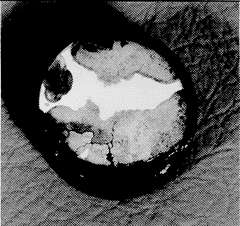 Figure 2. Dezincification of a 60-40 brass stem from a bronze valve
Valve seats, particularly those in throttling service, experience high water velocities, and data from (6) show that materials with high resistance to fast flowing seawater are stainless steels, nickel-base alloys and Monel alloy 400. Experience shows that when manufacturers upgrade the body material they often use the same materials for seats and stem as in a cast iron valve, i.e., 60-40 brass. Under these conditions the life of the valve internals is extremely short because, having lost the cathodic protection of the ferrous body, they fail by dezincification in a few months. Figure 2 shows dezincification of a 60-40 brass stem from a bronze valve. This is probably the most common cause of failure in non-ferrous valves. Although this type of corrosion is well-known, the rate of attack is often surprisingly high. The sample in Figure 2 failed in less than one year – the original diameter was 25 mm.
Although stainless steel (AISI Type 316) will give good life in a non-ferrous valve, it is liable to pit (particularly in crevices) when the system is not in use and on a life cycle cost basis, the nickel-copper alloys are a better choice. Another problem with stainless steels is the frequent use of steels of lower alloy content than Type 316 and these can pit very rapidly in seawater. Such materials are 12% Cr (AISI Type 410) and 18% Cr (AISI Type 430) stainless steels. Use of these alloys in seawater systems often results in early failure.
In ball and butterfly valves, one of the seats may be non-metallic, e.g., an elastomer.
InconelTM alloy 625 which has high resistance to both static and flowing seawater has been used as a weld overlay to produce highly resistant surfaces in critical areas of valves and shafts and also on pump castings. This alloy has excellent weld deposition characteristics and can be used as a general purpose overlay for avoidance of, or repair to, areas of corrosion damage in carbon, low alloy and stainless steel components.
Effect of Valve Design on Materials Selection
 Figure 3. Valve design
Valves are a relatively expensive part of a seawater system but the cost of a valve depends on the design used. Figure 3 shows some commonly used valve designs and gives an indication of their weight and pressure loss. Apart from any manufacturing difficulties, it is evident that a globe valve will be much more expensive than a butterfly valve because of its much greater weight. It will usually be more satisfactory to select reliable materials for valves, such as a butterfly valve, rather than to use an expensive design of valve, for example, a globe valve and try to economize on materials. Where the use of a globe valve is desirable, for example, for its good flow control characteristics, then the extra cost of corrosion resistant materials appropriate to the design must be accepted.
Some designers attempt to avoid corrosion problems by lining the valve. This is also related to the valve design; for example, butterfly valves are a simple shape and the body can be provided with a thick rubber lining which can be clamped firmly between the flanges joining the valve to the pipes and is not dependent on perfect adhesion between the rubber and the body. A gate or globe valve, however, is of complex shape and a lining, to be successful, must adhere perfectly to the metal surface. Experience shows that such adhesion is difficult to achieve and linings in valves of this type often have a short life.
A rubber-lined butterfly valve has certain features which must be considered in order to avoid corrosion problems. For example, the shafts, on which the butterfly turns, penetrate the lining and it is necessary to provide a positive seal between the lining and the stem to prevent access of seawater to the cast iron body. Failure to do this has resulted in valves failing due to corrosion products building up behind the lining causing seizure of the butterfly and stem.
Another commonly used seawater system valve is the membrane valve. This consists of a flexible membrane – usually of rubber – which separates the valve internals form contact with seawater. When operated, the membrane is extended into the stream restricting or shutting off flow. The shape is again simple and rubber linings on the body are effective. Cavitation damage to the rubber membrane can occur with severe throttling.
It is interesting to note the complex flow path within a globe valve. Several sharp changes of direction occur inside the valve and this gives rise to severe turbulence which can cause impingement corrosion on the valve body. Materials of high impingement resistance, such as nickel aluminum bronze or cast 70-30 Cu-Ni, are recommended when this type of valve is chosen.
Table 4 provides a summary of materials suitable for seawater valves in non-ferrous systems.
| Type of valve | Body material | Ball, disc, or seat material | Stem material |
|---|---|---|---|
| Butterfly valves | Gunmetals, 5% nickel aluminium bronze, Rubber-lined cast iron (provided a seal is fitted at the stem), Cast 70-30 Cu-Ni | 5% nickel aluminium bronze, Cast 70/30 Cu-Ni, Cast Monel alloy, Stainless steel (Type 316) | Monel alloys 400 or K-500, Stainless steel (type 316), 5% nickel aluminium bronze |
| Globe, gate, or ball valves | As above, except that rubber lined valves should be avoided | As above | As above |
| Membrane valves | Rubber lined cast iron | Rubber (membrane) | Not critical as there is no seawater content |
Galvanic Considerations in Valves
From Figure 4, it is evident that all the copper-base alloys have similar potential and can be used together without fear of serious galvanic effects. Where carbon steel or cast iron bodies have been fitted with brass trim, these will have received considerable galvanic protection from the large area of ferrous material and may give a useful life. Upgrading the body material to copper-base alloys will, by removing the cathodic protection effect, give rise to corrosion of the trim.
 Figure 4. The galvanic series in seawater
It is good practice to arrange for the trim material to be cathodic to the body, hence the use of alloys such as Monel alloys 400 and K-500 and stainless steels.
The use of copper-alloy valves is desirable in copper-alloy pipe systems so as to retain galvanic compatibility. The use of unprotected ferrous valves in non-ferrous systems should be avoided.
For stainless steel systems, galvanic compatibility is not a problem in the system itself, even though different alloys may be used for different components. Care is needed, however, if stainless steel is used to supply copper alloy heat exchangers as there can be a pronounced galvanic effect between them. This can be taken care of by fitting anodes in the waterboxes; iron, zinc or aluminum anodes can be used. Because iron ions in the seawater are beneficial for copper-base alloys, the use of iron anodes is advised.
Seawater Pumps
Centrifugal pumps are normally used in seawater systems and are often driven by constant speed electric motors. At the normal speed of rotation, the tip speed of the pump impeller can reach 20 m/s and at this velocity, most copper-alloys corrode rapidly in seawater. Fortunately, however, only certain components of the pump are exposed to these high velocities, and apart from these components, copper-base alloys can usually be used successfully in copper alloy systems.
Pump Casings
In copper alloy pumps, there is normally sufficient clearance left between the impeller and the casing so that the water flowing from the impeller does not impinge directly on the casing but is absorbed into the slower moving stream of water flowing over the metal surface towards the pump delivery pipe. Provided direct impingement is avoided, then materials such as gunmetals, aluminum bronze and cast 70-30 Cu-Nis perform satisfactorily. However, there have been cases of premature pump casing failures in recent years(18) showing that direct impingement can occur. This may be due to increase in pump speed or the tendency to uprate the output from standard pump designs. Where such failures have been experienced, the life of the casing has been very short, for example, about 18 months. To avoid failures of this type, either the design must be amended so as to reduce seawater velocity at the metal surface, or materials of higher resistance must be used. Experience shows that cast 70-30 Cu-Ni and 5% nickel aluminum bronze have higher resistance than gun metal or tin bronzes. Recent research, however, has shown chromium-containing 70-30 Cu-Ni to have higher resistance than other copper-base alloys to fast flowing seawater, as shown in Table 3.
Where pump parts are fabricated by welding from nickel aluminum bronze plate, there is a serious risk of selective phase corrosion (dealuminification) in the heat effected zone of the weld. This can crack if stressed, e.g., by water hammer effects.
Pump Impellers
The pump impeller is in contact with fast flowing, highly turbulent seawater and, for circulating pumps which are in use for most of the time, they should be made from a material with high resistance to these conditions. Table 5 provides corrosion data in high velocity seawater for several pump materials.
It is clear from Table 5 that the use of cast iron or mild steel can only be contemplated in pumps operated occasionally. From data in Table 5, Monel alloys 400 and K-500 and stainless steel Type 316 have very high resistance to flowing seawater, and cast versions of these alloys are preferred for pump impellers.
| Alloy | Corrosion rate | Seawater Velocity |
|---|---|---|
| mm/yr | m/s | |
| Grey cast Iron | 13 | 38 |
| Carbon steel | 9.5 | 40 |
| Monel Alloy 400 | 0.010 | 43 |
| Monel alloy K-500 | 0.010 | 43 |
| Stainless steel | 0.005 | 43 |
These alloys do not suffer from impingement attack but may pit when the pump is stationary and full of seawater. It should be noted, however, that the pitting likely to be experienced is often less severe than the general impingement corrosion which may occur at the tip of a copper-base alloy impeller and hence stainless steel or cast Monel Alloy 400 are preferred for this application.
Waterboxes
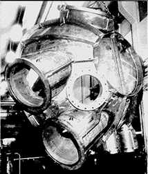 Figure 5. Fabricated 90-10 Cu-Ni waterbox
The commonest materials for waterboxes are cast iron or mild steel, and these are often rubber or plastic lined to extend their life. Unlined boxes, as used in older installations, corroded and helped protect the tubes and tube plates. However, the corrosion of the waterbox itself is a serious problem and there is a trend towards non-ferrous boxes, particularly for condensers. Figure 5 shows a fabricated 90-10 Cu-Ni waterbox for a ship condenser. The use of this type of construction is economic, as all the external stiffening is carbon steel and only the metal in contact with seawater is Cu-Ni.
Waterboxes in nickel aluminum bronze are also used, particularly with titanium tubes because of galvanic considerations. These are usually cast – fabrications may require cathodic protection to avoid selective corrosion on welds (see piping section).
Strainers
The purpose of strainers is to filter out materials detrimental to the system, for example, to minimize fouling and plugging of heat exchanger tubes.
Primary filtration is usually by a fairly robust grid or trash rack to eliminate large pieces of debris such as bottles and pieces of timber. These are usually made of steel or cast iron protected by paint and/or cathodic protection.
Trash racks are usually followed by stationary or traveling screens in the intake system and by fine filters within the system itself. Details of materials for these screens is given in (17).
One important aspect of filtration is the removal of air from the system. Air can markedly enhance the erosion-corrosion effect of seawater and thus stimulate impingement attack on copper-base alloys. Provision should be made for air release from the high parts of components where it may accumulate, for example, waterboxes.
Interactions within the System
Galvanic Effects
Wherever possible, components of similar galvanic potential should be used for construction of the system. Where this is not possible, the following guidelines should be used:
- Make the "key" component of a more noble material. For example, use copper-base alloy trim in a cast iron valve body.
- Ensure that the material of lower potential is present in a much larger area than the more noble material so that the accelerated corrosion of the anode is spread over a large area.
- Paint the more noble material. This can be beneficial as it reduces the cathode area even when the paint film is incomplete. An imperfect paint film on the anode would intensify attack at breaks in the paint.
Replacement of cast iron or fabricated steel waterboxes by rubber-lined or non-ferrous components will remove the beneficial galvanic effects on tube inlet ends provided by the ferrous components. This may lead to tube inlet end erosion, and either an alloy with higher impingement resistance should be used, or steel anodes should be fitted in waterboxes.
Titanium tubes have a strong galvanic effect on most copper-base alloys and can stimulate corrosion on Cu-Ni waterboxes and tubeplates. Care is needed to avoid galvanic corrosion when titanium tubes are used – also for Cu-Ni nozzles in titanium plate-type exchangers. The galvanic effects can be controlled by cathodic protection but care is needed to ensure that overprotection does not cause hydriding of the titanium tubes.(18)
Chemical Additions
Chlorine is often added to seawater – to prevent marine growth which would cause tube blockage resulting in loss of heat – transfer or impingement attack. Care must be taken in adding chlorine as excess chlorination can produce corrosion effects on steel and copper base alloys. Work by Anderson and Richards (19) shows that control of fouling can be achieved without detriment to materials if the chlorination is carefully controlled. This is best done by measuring the residual chlorine at the plant outlet and adjusting the chlorine dose to maintain this at a low level, e.g. 0.1-0.2 ppm.
Another substance commonly found in seawater systems is the ferrous ion. In older systems with ferrous components, corrosion of these components provided a continuous supply of ferrous ions which, experience has shown, had an effect on corrosion of copper-base alloys, notably aluminum brass tubes. In modern systems, where the supply of ferrous ions may be largely eliminated either by use of non-ferrous materials or by use of coating, failures of aluminum brass heat exchange tubes have been experienced.(16) This can be rectified either by deliberately injecting ferrous ions into the system or by fitting Cu-Ni tubes which are less affected by ferrous ions in the water.
Conclusion
By treating seawater systems as a whole it is possible to build corrosion resistant, reliable systems with low maintenance costs.
Table 6 summarizes the information in this paper and suggests materials which can be used to achieve these objectives or, by accepting higher maintenance costs and lower reliability, to build a system with minimum initial costs. It should be emphasized that systems consisting of partial adherence to the two approaches suggested are likely to result in higher initial costs and lower reliability.
| Minimum first cost - high maintenance cost system |
Component | High reliability - low maintenance cost system |
|---|---|---|
| Copper-base | ||
| Galvanized steel | Pipe | 90-10 Cu-Ni |
| Steel | Flanges | - Cast or forged 90-10 Cu-Ni
|
| 60/40 brass/naval brass | Tubeplates | - Nickel aluminium bronze - 90-10 Cu-Ni |
| Aluminium brass | Tubes | - 70-30 Cu-Ni (particularly 2% Fe + 2% Mn) - 90-10 Cu-Ni |
| Cast iron or leaded Gunmetal | Pump casing | - Cast Cu-Ni - Nickel aluminium bronze - Admiralty Gunmetal - Ni-resist Type D2 |
| Gunmetal | Pump impeller | - Monel Alloy 410 - Alloy 20 (CN7M) - Stainless steel (CF3 and CF8) - Nickel aluminium bronze |
| Naval brass | Pump shaft | - Monel Alloy 400 or 500 - Stainless steel (type 316) - Nickel aluminium bronze |
| See Table 4 | Valves | See Table 4 |
| Cast iron | Strainer body | - Ni-resist iron type D2 - Nickel Aluminium Bronze - Cast Cu-Ni - Gunmetal |
| Galvanized iron | Strainer | Monel alloy 400 |
Appendix (Typical compositions of alloys commonly used in seawater systems)
| Alloy | Copper | Tin | Zinc | Aluminium | Other |
|---|---|---|---|---|---|
| Admiralty Gunmetal | 88 | 10 | 2 | - | - |
| Leaded Gunmetal | 85 | 5 | 5 | 5 | - |
| Leaded Gunmetal + nickel | 86 | 7 | 2.5 | - | 2.5% Lead 2% Nickel |
| Nickel aluminium bronze | 85 | - | - | 10 | 5% Iron 5% Nickel |
| Aluminium brass | 76 | 22 | 2 | 0.02% Arsenic |
| Alloy | Copper | Nickel | Iron | Other |
|---|---|---|---|---|
| 90-10 Cu-Ni | Remainder | 10 | 1.5 | 1.0 Mn (max) |
| 70-30 Cu-Ni | Remainder | 30 | 0.6 | 1.0 Mn (max) |
| 70-30 Cu-Ni (high iron) | Remainder | 30 | 2.0 | 2.0 Mn |
| 70-30 Cu-Ni+Cr | Remainder | 30 | 0.7 | 1.6 Cr |
| Ni-Cu Alloy 400 | 31.5 | 66 | 1.35 | 0.9 Mn |
| Cast Ni-Cu Alloy BS 3071 | 30.5 | 66 | 1.35 | 1.6 Si |
| Ni-Cu Alloy K 500 | 31.5 | 66 | 1.35 | 1.9 Mn 2.8 Al 0.5 Ti |
| Cast Ni-Cu Alloy BS 3071 NA3 | 29 | 64 | 2.0 | 4.0 Si |
References
- "Marine Corrosion." F. L. LaQue, Wiley Interscience.
- "Copper Alloys in Marine Engineering Applications." P. T. Gilbert and W. North. Trans. of the Institute of Marine Engineers, 1972, 84, Part 16 520.
- "Design Study of Condensers and Circulation Systems." S. A. Fielding, Marine Technology, April, 1971.
- "Sea Water Systems." W. H. Falconer and L. K. Wong. Institute of Marine Engineers, Materials Section. Symposium P. 26, London, 1968.
- of Materials Usage in Seawater Systems." D. Bailey. Project G30, May, 1982, BSRA.
- "Selection of Materials for High Reliability Seawater Systems." Supplement to Chemistry and Industry. 2nd January, 1977.
- BSMA 18. Salt Water Piping Systems in Ships.
- G. Butler and A. D. Mercer, Nature 1975. Vol. 256 Issue No. 5520. P 179-720.
- "Stainless Steels for Seawater Service," A. P. Bond, M. J Dundas, S. Eherot and M. Semchyshen. Stainless Steel '77 Paper 15.
- "Galvanic Action of Steel in Concrete." H. Arup. Korrosionscentralen Report, August, 1977.
- "Lined Steel Piping for Salt-Water Services." Final Report NS 460 British Ship Research Association.
- "Use of Cu-Ni Alloy Materials for Offshore Seawater Piping." L. H. Lim, Offshore Europe 77 Conference, Aberdeen.
- "Copper Alloys for Seawater Systems." P. T. Gilbert, Institute of Marine Engineers Symposium, London, March 1968.
- "Corrosion Resisting Properties of 90/10 Cu-Ni Iron Alloy with Particular Reference to Offshore Oil and Gas Applications." P.T. Gilbert, 7th International Congress on Metallic Corrosion, Oct. 4th-11th, 1978. Rio De Janeiro, Brazil. Paper No. 126.
- "The Effects of Fluid Dynamics on The Corrosion of Copper Base Alloys in Seawater." K. D. Efird, Corrosion '76 Conference, Houston, March, 1976.
- "Problems in Seawater Circulating Systems." E. B. Shone, British Corrosion Journal 1974, No. 1. pp. 32-38.
- "Lower Cost Water by Proper Materials Selection." Proceedings of 3rd European Symposium on Fresh Water from the Sea. pp. 549-578.
- "Characterization of Titanium Condenser Tube Hydriding at Two Florida Power and Light Company Plants." J. P. Fulford, R. W. Schutz, R. C. Lisenbey. Joint ASME/IEEE Power Generation Conference, Miami Beach, Florida, October 4-8, 1987.
- "Chlorination of Seawater - Effects on Fouling and Corrosion." D. B. Anderson and R. B. Richards, Journal of Engineering for Power, July, 1966.