Contents
- Condenser and Heat Exchanger Tubes
- Tubesheets
- Piping
- Fittings
- Tube and Pipe Bending of Copper Nickel
- Pumps
- Valves
- Water Boxes
CONDENSER AND HEAT EXCHANGER TUBES
Applications of Condenser and Heat Exchanger Tubes in Copper Alloys
| Industry | Application |
|---|---|
| Power Station | Condenser, feed water heater, air ejector, water cooler, oil cooler, hydrogen cooler |
| Nuclear Power Station | As above plus mist separator |
| Shipping | Main condenser, auxiliary condenser, drain cooler, feed air heater, air cooler, steam generator, refrigeration, air conditioning, tank heating coils, hydraulic system |
| Petrochemical | Process heat exchanger, cooler and condenser, process reboiler, boiler feed heater, oil cooler, generator turbine condenser, air compressor inter and after cooler |
| Chemical Industry | As above |
| Desalination | Heat exchangers for heat recovery, heat rejection and brine heater sections |
| Refrigeration, ventilation and Air conditioning | Condenser, brine evaporator, heater etc |
The upper working temperature for 90-10 and 70-30 Cu-Ni is normally about 250°C.
USEFUL REFERENCES/LINKS:
- Copper Nickel Condenser and Heat Exchanger Systems; W. Kirk and A. Tuthill; CDA Inc Seminar Technical Report 7044-1919. The Application of Cu-Ni Alloys in Marine Systems.
- Fine Wall(22BWG) 90-10 and 70-30 Cu-Ni Condenser Tube Use at the Hennepin Energy Resource Company Power Plant; W.E. Helliwell and G.A. Anderson; PWR-Vol 30 1996. Joint Power Generation Conference Vol 2 ASME. 1996.
- System Design
- The Use of Cathodic Portection for Copper Alloys in Seawater Cooling Systems; by L. Berthagen; Eurocorr 2001 Marine Corrosion Working Party Meeting.
- Wolverine Engineering Data Book II.
- Wolverine Engineering Data Book III.
Velocity
Heat exchangers are designed for flow rates more than 1m/s. The higher the velocity the greater the heat transfer efficiency but velocity is limited by pumping cost, pressure drop across passes, tolerance limits of materials. Normally design velocity for Cu-Ni is 1.8-2.5m/s based on uniform non-turbulent flow through the system.
| Typical maximum velocities for diameters less than 25mm. | |
|---|---|
| 90-10 | Unpolluted sea water about 2.5m/s. With entrained sand, 2.0m/s Fresh water: about 4m/s |
| 70-30 | Unpolluted sea water about 3.0m/s. With entrained sand 2.4m/s |
| 66-30-2-2 | Unpolluted sea water 4.5m/s. With entrained sand 3m/s |
Commissioning, Operation and Shutdown
- Care and Maintenance of Copper Alloy Tubed Condensers-Construction Through Early Life. William Sartor; CDA Heat Exchanger Seminar 1981.
- Heat Exchanger and Piping Systems from Copper Alloy- Commissioning, Operating and Shutdown; M.Jasner et al.; KME publication 1998.
- Protection of Seawater System Pipework and Heat Exchanger Tubes in HM Surface Ships and Submarines in Sea Water Systems; UK Ministry of Defence Standard 02-781 Issue 2; May 2009.
- System Design.
TUBESHEETS
Tubesheets should not be more noble than the tubes as this can cause a galvanic influence on the corrosion rate of the tube ends. Therefore 90-10 Cu-Ni tubesheet can be used with 90-10 Cu-Ni tubes. Also, Naval brass, Muntz metal and aluminium bronzes are slightly anodic to 90-10 Cu-Ni tubes and are therefore compatable.70-30 tubes should have 90-10 or 70-30 tubesheets. For clad tube sheets, welded tube to tube sheet joints are preferred.
There are many different tube/tube sheet (T/TS) weld joint designs used in industry and each has their particular advantages and disadvantages. The more common joints are the flush tube, recessed tube, trepanned tube sheet, added-ring and face side fillet weld when the weld is made on the tubesheet face.
(see Copper-nickel Welding and Fabrication; Published by CDA In as A7020-99/13. Nickel Institute as 12014. Second Edition and CDA UK as Publication 139 Second Edition.)
Joining Tubes-to-Tubesheet
In heat exchangers and condensers, tubes are joined to tubesheets to prevent leakage between the tube side and shell side. Often the easiest and least expensive method is to mechanically expand the tube into the drilled hole in the tubesheet usually by roller expansion. Ideally the tubesheet should be harder than the tubes. A mechanically expanded joint may be acceptable when :
- Service temperatures are low e.g. under about 200°C
- Tube sheets are sufficiently thick to allow rolling-in a suitable length of tube
- Design pressures are relatively low
- A weld joint is not needed to support the tube bundle
A mechanical joint is not used for severe services where a leak could present a catastrophic safety hazard.
When a tube-to-tubesheet weld is made in a Cu-Ni construction, it is most often an automatic gas-shielding tungsten arc (TIG) weld made either with or without filter metal. Manual welding might be used on special designs and is often the standard method for weld repairing. With manual welding filler metal addition is recommended, particularly to avoid porosity from lack of complete gas shielding over the molten weld metal. While the TIG process is well adapted to make T/TS welds with thin wall tubes, other welding processes may be better suited for large diameter and thinner wall tubes. Alternate welding processes include manual metal arc (MMA), metal inert gas (MIG) or plasma arc. Explosion welding is another joining option although it is seldom used in Cu-Ni construction.
There are many different T/TS weld joint designs used in industry and each has their particular advantages and disadvantages. The more common joints are the flush tube, recessed tube, trepanned tube sheet, added-ring and face side fillet weld when the weld is made on the tubesheet face.
Selection of a particular automatic TIG weld joint configuration involves considerations such as the following:
- joint crevice leak path size requirement
- filler metal requirements
- tubesheet heat sink
- structural flexibility
- available equipment
- tube dimensions and ligament size
Successful T/TS welding depends to a very high degree on the accurate machining of holes, joint preparation on the tubesheet and cleaning all surfaces prior to welding. Accurately machined holes are particularly essential for automatic welding to assure the tungsten electrode is always positioned correctly in the weld joint. Cleaning problems start with the contamination of the tubesheet by the hole drilling lubricants. The tubesheet should be cleaned immediately after drilling and positioned so that during cleaning the contaminants drain from the tubesheet and do not accumulate on one surface. Compressed air should not be used to 'blow off' the cleaning solution unless equipment is installed to remove the normal moisture and oil contamination. Dry nitrogen is often a good alternative to compressed air.
Prior to T/TS welding, it is often desirable to expand the tube into the tubesheet, for example by a 'light roll' to assure the tube is centred in the hole for good tracking in automatic welding. A 'hard roll' prior to welding increases the chance of producing a weld defect from escaping gas as the weld is being made. After the T/TS weld is made on thicker tubesheets, the tube is often given a 'hard roll' stopping about 25 mm short of the back side.
A visual inspection should be made for weld defects in the completed T/TS weld. A liquid penetrant inspection of the welds is also quite standard. Other inspections that might be imposed are a leak test and in some T/TS designs a radiographic inspection can be made of selected areas. Defects such as cracks or porosity should be ground out and a manual TIG repair with filler metal made.
USEFUL REFERENCES/LINKS:
- Copper Nickel Condenser and Heat Exchanger Systems; W. Kirk and A. Tuthill; CDA Inc Seminar Technical Report 7044-1919. The Application of Cu-Ni Alloys in Marine Systems.
- Heat Exchangers and Piping Systems from Copper Alloys Commissioning, Operating and Shutdown. KME Publication.
- Tube/Tubesheet Joining. Carl Gaffoglio; CDA Heat Exchange Seminar 1981.
PIPING
Cu-Ni is used for piping systems in a wide range of sizes. Attention to velocity limits and good commissioning practices are the main requirements to achieve excellent service.
USEFUL REFERENCES/LINKS:
- Protection of Seawater System Pipework and Heat Exchanger Tubes in HM Surface Ships and Submarines in Sea water systems; UK Ministry of Defence Standard 02-781 Issue 2; May 2009.
- Materials Selection for High Reliability Sea water systems; B.Todd. CDA Inc Seminar Technical Report 7044-1919. The Application of Copper Nickel Alloys in Marine Systems.
- Heat Exchangers and Piping Systems from Copper Alloys Commissioning, Operating and Shutdown. KME Publication.
- Cu-Ni Seawater Piping Systems. G. Wildsmith. Proceedings of Marine Engineering with Copper Nickel. London April 1988.
- The Design and Installation of 90-10 Sea water Piping Systems. Nickel Development Institute Publication 1107.
- Typical Failures of 90/10 CuNi Sea water Tubing Systems and How to Avoid Them. W Schleich. Eurocorr 2004, NICE, September 2004.
- Sea Water System Design.
- Application of Copper-Nickel Alloy UNS C70600 for Seawater Service. W.Schleich. Paper 5222 Corrosion 2005. (©NACE).
FITTINGS
For a description of fittings and their properties, see System Design section.
Back to TopTube and Pipe Bending of Copper Nickel
This section covers tube bending methods, gives a detailed illustration of rotary draw bending and describes bending defects and how to correct them.
Tube Bending Methods
Various methods can be used for bending tubes depending on the material in use and the required precision. The more common procedures are rotary draw bending, 3-roll bending, compression bending and ram bending (press bending) ( Figure 1).
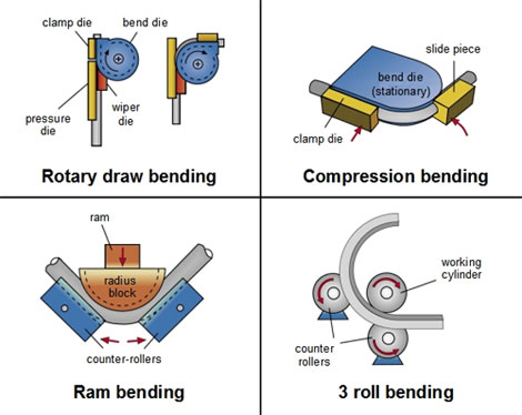 Figure 1
Rotary Draw Bending
When rotary draw bending is applied, the tube is fastened between the bend die and the clamp die. The rotation of both tools around the bending axis bends the tube to the radius of the bend die. The pressure die (slide piece) serves the purpose of receiving the radial stress, which is generated during the forming process, and supports the straight tube end from outside. If a mandrel and wiper die are additionally applied (mandrel bending), a high quality work piece can be achieved even with thin-walled pipes and tight bending radii.
Compression Bending
Compression bending is similar to rotary draw bending. This bending method is carried out with a sliding carriage and a stationary bend die, between which the tube is clamped. The sliding carriage, which rotates around the radius block, bends the tube to the radius of the bend die.
Ram Bending (Press Bending)
When ram bending is applied, a radiused bending tool is pressed against two counter-rollers, either manually or by means of hydraulics. This motion forces the tube inserted between the radius block and the counter-rollers to bend around the radius. The tube cannot be supported from within, therefore this method is suitable for thick-walled tubes and large bending radii only.
3-roll Bending
3-roll bending is also used for producing work pieces with large bending radii. The method is similar to the ram bending method, but the working cylinder and the two stationary counter-rollers rotate, thus forming the bend.
Rotary Draw Bending
Rotary Draw Bending is the most versatile and precise bending method ( Figure 2). It consistently produces high quality bends, even with tight radii and thin tube walls.
 Figure 2
The following tools are required for pipe bending ( Figure 3).
- Bend Die
- Clamp Die
- Pressure Die
- Mandrel
- Wiper Die
 Figure 3
 1. Bend Die
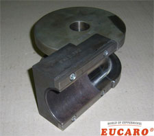
 2. Clamp Die
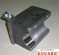
 3. Pressure Die
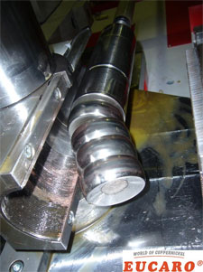 4. Mandrel
 5. Wiper Die
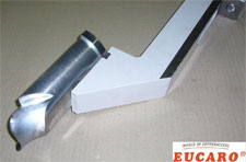 5. Wiper Die
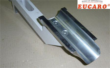
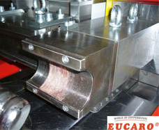
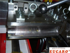
For rotary draw bending, the tube is inserted into the bending machine and clamped between the bend die and the clamp die. Figure 4 shows the bending process as described earlier.
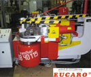 Figure 4

When bending Copper-Nickel, a mandrel and wiper die are also applied (mandrel bending).
With modern mandrel bending machines, almost any kind of cold-formable tubes - depending on the applied material - can be bent to bending radii of approximately 1xD to 5xD (referring to the outer diameter of the pipes), safely and with the desired precision.
Today, the main differences in rotary-draw-bending machines are the maximum workable outside tube diameter and the degree of automation of the various functions. Only the bending function of so-called "1-axis controlled" bending machines is automatic; feeding and rotation of the tube between two bends are carried out manually.
For the user of CNC (Computer Numeric Control) or bending machines with fully automatic control, however, all functions are available automatically. These bending machines can be supplemented with automatic feeding and unloading systems for large production runs without any problems.
Bending Failure - Defects and Corrections
 Defect
Wrinkling throughout bend, even extending into wiper die area.
Correction
1. Advance wiper die closer to tangent.
2. Decrease rake of wiper die.
3. Recut worn wiper. Defect
Wrinkling throughout bend area with wiper and mandrel in known proper position.
Correction
1. Check for undersized mandrel.
2. Increase pressure die force only after checking wiper fit and mandrel location.
3. Reduce force on pressure die advance. Defect
Excessive collapse with or without wrinkling throughout entire bend.
Correction
1. Advance mandrel toward tangency until slight hump occurs (most mandrels must project to a certain extent past tangent).
2. Need more balls on mandrel. Defect
Heavy wrinkles through bend area only and linear scratches in grip area indicating clamp slippage.
Correction
1. Reduce pressure force.
2. Check location of mandrel and wiper die (and lube).
3. Increase pressure on clamp die.
4. Use serrated or carbide spray in tube groove of clamp die. Defect
Wrinkling occuring for only a portion of the bend (45° out of 90°).
Correction
1. Check if bend die is out of round or there is a bad centering ring or counter bore.
2. Check if there is a taper in the pressure die (from bottom of tube). Defect
Buckle at the end of the bend.
Correction
1. Adjust mandrel slightly back from the tangent until the buckle is barely visible.
2. Increase force on pressure die assist Defect
Mandrel ball humps.
Correction
1. Too much drag on tube; back off pressure die force-increase wiper die rake.
2. May require closer pitch mandrel ball assembly.
3. Tubing material too soft.
4. Increase force on pressure die assist. Defect
Tool marks on centerline of bend.
Correction
1. Re-adjust vertical alignment of clamp and/or pressure die.
2. Undersized tube groove in bend die. Defect
Tool marks on centerline of bend in clamp and pressure die area.
Correction
1. Reduce pressure and clamp die forces.
2. Check for oversized tube or undersized tube groove from bad tooling source. Defect
Bad mark at start of bend and over bend for 90°.
Correction
1. Check if removable clamping portion of bend die is not matched properly to round part of bend die.
2. Check if clamping portion of bend die is not parallel to the key way. Defect
Excessive collapse after tubing is pulled off mandrel balls.
Correction
1. Check for too much drag on tube; back off pressure die force; increase rake on wiper die.
2. Increase mandrel to support; change from a plug to a one ball; a 3 ball instead of a 2 ball mandrel. Defect
Deep scratches throughout the bend and in wiper die area.
Correction
1. Increase rake.
2. Check for undersized mandrel.
3. Increase pressure die force only after checking wiper fit and mandrel location.
4. Reduce force on pressure die advance.
5. Use more and/or a better lubrication.
PUMPS
Centrifugal pumps are often used in seawater systems; the main components being the casing and the impeller. Cast alloys such as gun metal, nickel aluminium bronze and cast copper nickel can be suitable for the casing in copper based piping systems with alloys of resistance to higher water velocities for the impeller such as alloy 400 or nickel aluminium bronze. Appropriate attention has to be given to galvanic considerations when selecting materials.
USEFUL REFERENCES/LINKS:
- Materials Selection for High Reliability Seawater Systems; B.Todd; CDA Inc Seminar Technical Report 7044-1919. The Application of Copper Nickel Alloys in Marine Systems.
VALVES
The three main components of a valve are the body, seats and shafts or stems. Copper based alloys such as nickel aluminium bronze, gun metals and cast copper nickels are often used for valve bodies with alloys which are more noble and have resistance to fast flowing sea water for the seat or stem.
USEFUL REFERENCES/LINKS:
- Materials Selection for High Reliability Seawater systems; B.Todd; CDA Inc Seminar Technical Report 7044-1919. The Application of Copper Nickel Alloys in Marine Systems.
WATER BOXES
90-10 and 70-30 Cu-Ni alloys are widely used for water boxes in ships and desalination service.
USEFUL REFERENCES/LINKS:
- Copper Nickel Condenser and Heat Exchanger Systems; W. Kirk and A. Tuthill; CDA Inc Seminar Technical Report 7044-1919. The Application of Cu-Ni Alloys in Marine Systems.
- Materials Selection for High Reliability Sea water systems; B.Todd; CDA Inc Seminar Technical Report 7044-1919. The Application of Copper Nickel Alloys in Marine Systems.