- Introduction
- Water Quality
- Intake System
- Corrosion Resistance
- Materials Selection
- Conclusions
- References
Introduction
For the vast majority of heat transfer equipment applications, the transfer of heat takes place between two fluid streams. The heat exchanger is simply a device which directs the flow paths in such a way that the two streams are brought into thermal contact through a conducting wall while being kept physically separate. This thermally conductive wall is the tube in shell-and-tube type heat exchangers that make up a large percentage of such units in power plants, ships, the chemical process industry and in desalination. The relatively thin-walled tube, selected primarily for heat transfer efficiency, becomes the critical component in condensers and other heat exchangers and must perform well over long periods of time under sometimes very difficult operating conditions. Cu-Ni alloys have established a long and successful history in seawater cooled heat exchangers and will be emphasized in this paper.(1-7)
Since the condenser is the heart of the heat reject system in operating power or process industry plants, as well as in ships, its reliability and efficiency affect the overall system performance. Deposits and films which accumulate and grow on the tube's inside surface affect heat transfer capacity and in turn its ability to condense steam. This paper will discuss the influence and control of these films as important parts of tube integrity that maintain the interface between a highly controlled thermodynamic working fluid and a potentially aggressive cooling water.
Natural seawater, that may or may not be polluted, will be considered the cooling water for all discussions. Coastal plants are usually designed to have one large heat exchanger with seawater on the tube side and multiple, closed loop cooling systems on the shell side. Heat exchanger materials must be selected to handle steam or other working fluids in these shell side circuits, as well as the available on-site cooling water on the tube side. While these closed loop circuits have their own criticality in terms of thermodynamics, mechanics and operating maintenance, this paper will concentrate on the tube-side (sea water) characteristics. Any leakage from the tube side will readily contaminate whatever working fluid is on the shell side. The effects of contamination must be considered throughout the process, from design to materials selection to maintenance, for the operating age of the total system.
In regard to tubing performance, several interactions with other components of the cooling water system must be considered:
- First in importance is the debris removal equipment ahead of the waterbox or channel head. This is discussed in more detail in the section on the Intake System.
- The design and operation of the chlorine injection system is discussed in the section on Corrosion Resistance. Even after extensive screening out of debris and marine organisms, free swimming larvae enter the waterbox and tubing and can attack and grow if given the opportunity.
- The design velocity and flow pattern from the waterbox through the tube bundle can affect the corrosion and heat exchange performance of the tubing. Refer again to the section on Corrosion Resistance.
- Galvanic interactions among the materials of the waterbox, tube sheet and tubing are also discussed in the Corrosion Resistance section.
Water Quality
Usual seawater analyses will include temperature salinity or conductivity, dissolved oxygen, pH and sometimes metal ions if a known source is nearby. The presence or absence of oxygen, hydrogen sulfide (H2S) and industrial pollutants (especially ammonia) are compositional factors that have a significant effect on copper alloy performance in heat exchanger systems and must be identified. While not normally included in water analyses, the debris loadings (sticks, stones, gravel, sea shells, mud and sand), dissolved gases and free swimming larvae of the biofoulers often have a far greater effect on tube performance than the compositional factors reported in the usual water analyses.(8-10) Water pollution increased in the United States around mid-century under the dual impact of industrial waste and untreated municipal sewage until the 1960s. Federal and state legislation then reversed this trend, and concurrently pollution related tubing failures that had peaked in the early 1960s began to decline.
Environmental legislation has had other effects on the handling of cooling water.(11) At the point of discharge, both temperature and the manner in which the discharge water is dispersed is usually regulated to a maximum temperature differential in relation to the ambient temperature of the receiving body of water. In addition, the Environmental Protection Agency (EPA) limits residual chlorine to 0.2 ppm average in effluent streams.
The net effect of the environmental legislation was a change in the corrosive nature of the cooling waters. It increased biofouling activity once again, so that the full impact of biofouling had to be dealt with in existing installations as well as the design of new ones.
Intake System
Design, operation and maintenance of the seawater intake system has a profound effect on heat exchanger tubing performance. Shipboard systems are relatively simple, since ships operate in large bodies of water with very low debris loadings and quite clean seawater, except in port. These intake systems include a grate, flush with or slightly recessed in the hull, to keep out large items such as boxes, fish or floating logs. Stationary screens or strainers are normally provided between the pumps and the waterbox to screen out smaller debris. Additional screens with small openings are essential ahead of small diameter tubes in auxiliary exchangers such as oil coolers and keel coolers.
Figure 1. Function of the bar grates and traveling screens in a seawater intake system
The design of the intake system for coastal plants is much more elaborate and more critical. Figure 1 illustrates the function of bar grates and traveling screens. Large floating debris is kept out of the inlet by the bar grates. Water velocity through the bar grates must be low enough so that fish and trash are not held against the screens, thereby reducing the flow area and increasing velocity through the screens. Any increase in water velocity will simply hold more trash and fish, further reducing flow area and further increasing water velocity.
The traveling screens downstream of the bar grates are designed to screen out fish, crab claws, sea shells, twigs, polyethylene bags and similar trash. These screens are designed to discharge accumulated trash as they slowly rotate. Traveling screens must be maintained in good operating order. The hole size in the traveling screens is on the order of 1/2 inch or less, and the heat exchanger tube size is usually set at a minimum of two times the screen opening.
 Figure 2. Schematic drawing of section of a seawater intake system between the traveling screens and the heat exchanger
Figure 2 illustrates the section of the cooling water system between the traveling screens and the exchanger or condenser. The stationary screens, which may be basket or automatic strainers or filters, provide the final screening of debris before the cooling water enters the waterbox and tubing.
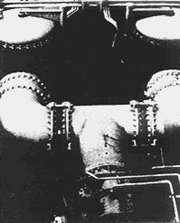
Figure 3. Two basket type strainers in a large desalination plant

Figure 4. Course debris removed from bottom of a strainer (Figure 3)
Figure 3 is a photograph of two such basket-type strainers in a Mideast desalination plant. The coarse debris, shells, rocks, glass, a nail and a piece of steel in the upper part of Figure 4 were removed from the bottom of one of these two strainers. Shells and smaller stones shown in the lower part of Figure 4 were removed from the discharge side of the tube bundle. The screen in the strainer had been broken by the larger rocks, nail and steel, allowing the latter mentioned debris to reach the tubes. Screen openings were 3/8 inch, which kept debris large enough to cause lodgements out of the tubing until the screens were broken. Some of the debris had lodged in the tubes leading to penetration of the tubing downstream of the lodgements, similar to that shown in Figure 5 and Figure 6.
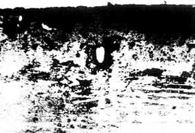
Figure 5. Penetration of tube downstream of lodgement
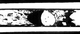
Figure 6. Stone lodged in a tube with hole downstream
The desalination plant operators identified and recorded the failures as tube failures; whereas, they were really screen failures. It is absolutely essential that screens in the intake system be properly designed, and it is equally essential that they be properly operated and maintained. Tube failures from debris lodgements are screen failures and should be recognized as such. Otherwise, the real cause of failures may be overlooked and quite unnecessary tube failures allowed to continue.
With two strainers, as in the above mentioned design, the plant operates one until it is plugged and then switches to the other. The strainer removed from service must be thoroughly cleaned and the screens repaired or replaced so that the strainers, not the tube bundle, will remove debris from the system. The condenser or heat exchanger should never function as a main filter or screen.
Corrosion Resistance
Corrosion Product Films
 Figure 7. Formation rate of corrosion product film on alloy C70600 in seawater
 Figure 8. Corrosion rates for alloy C70600 in long-term seawater exposures
The corrosion resistance of Cu-Ni alloys in seawater depends upon the nature of the corrosion product film that forms on the surface after it is wetted with water. Figure 7(12) shows the rate of film formation on C70600 (Cu-Ni alloy compositions are given in Table 1) tubing in clean seawater at 60F in terms of the reduction in copper in the effluent from one minute to three months after startup. Ten minutes after startup, the copper in the effluent had decreased tenfold, and one hour after startup by one hundredfold. After three months, the film was mature enough so that copper in the effluent was essentially the same as the copper level at the intake. The data in Figure 8 (13) confirm the increasingly protective nature of the film through 14 years of exposure. This long-term protective nature of the corrosion product film on Cu-Ni alloys (C71500 was also included in the 14-year tests yielding a long-term corrosion rate similar to that of C70600 7,14) is responsible for the 20-plus years' service life of alloy C71500 in shipboard condensers (15) and in many coastal plants (16).
| Element | C70600 Range | C71500 Range | C71640 Range | C72200 Range |
|---|---|---|---|---|
| NI | 9.0 - 11.0 | 29.0 - 33.0 | 29.0 - 32.0 | 15.0 - 18.0 |
| Cr | - | - | - | 0.3 - 0.7 |
| Fe | 1.0 - 1.8 | 0.4 - 1.0 | 1.7 - 2.3 | 0.5 - 1.0 |
| Mn | 1.0 max | 1.0 max | 1.5 - 2.5 | 1.0 max |
| Zn | 1.0 Max | 1.0 max | - | - |
| Pb | 0.05 max | 0.05 max | 0.01 max | - |
| Si | - | - | - | 0.03 max |
| C | - | - | 0.06 max | 0.03 max |
| Ti | - | - | - | 0.03 max |
| S | - | - | 0.03 max | - |
| Cu | Balance | Balance | Balance | Balance |
The normal corrosion product film is thin, adherent and durable. Once fully formed and reasonably mature, the film on Cu-Ni alloys will withstand considerable excursions in water velocity, pollution and other conditions normally adverse to the good performance of copper alloy tubing. Good, protective films will form in cold seawater (less than 20°C) but they take considerably longer time to mature.(17) Francis(18) observed at temperatures below 10°C that greater impingement attack was noted on alloy C71500 due to a lack of iron enrichment in the corrosion film. No such change was observed for C70600 nor the higher iron-containing alloy C71640. Corrosion rates and film formation at elevated temperatures were studied by Ross,(19) who observed that high bicarbonate alkalinity is beneficial to the formation of good films on C70600 at a temperature of 60°C. Film formation is retarded or prevented at pH levels below 5 in aerated seawater. Cu-Ni alloys remain resistant to corrosion in deaerated sea water at low pH as has been experienced in numerous distillation type desalination plants.(20)
Velocity Effects
The corrosion rate of copper alloys can be affected by seawater velocity above a certain limit identified for each alloy. The more adherent and protective the "passive" film on a particular alloy, the higher the "breakaway" velocity and the greater its resistance to impingement attack or erosion corrosion. Much information has been published on the effects of high sea water velocity vs. the corrosion of copper-base alloys. The desire to obtain better resistance to impingement attack led to the development of a new copper-base alloy C72200,(21) containing approximately 16% Ni and 0.5% Cr. Results of numerous impingement and erosion corrosion tests of copper, admiralty and aluminum brass, 90-10 and 70-30 Cu-Ni, and the chromium-containing Cu-Ni alloy yield the industry accepted design velocity limits for condenser tubing shown in Table 2.(22) Other tests included alloy C71640, containing 2% Fe and 2% Mn, and would indicate a velocity tolerance much greater than that of alloy C71500 but less than the limit for C72200.(7)
| Alloy | Maximum design velocity (m/s) |
|---|---|
| C12200 | 0.6 |
| C44300 | 1.2 |
| C68700 | 2.4 |
| C70600 | 3.6 |
| C71500 | 4.6 |
| C72200 | >9.0 |
| Minimum velocity to prevent sediment deposition and under deposit corrosion | 1.0 |
| Normal design velocity | 2.0 |
Two studies (23),(24) were conducted to characterize the behavior of Cu-Ni alloys under conditions simulating partial blockage of a condenser tube. In one-year natural sea water tests, enhanced resistance to erosion corrosion was observed for both the C72200 and C71640 alloys as compared to C70600 and C71500. Some localized corrosion (pitting or crevice attack) was noted on the two more highly alloyed materials but not on the standard alloys. This observation was also noted in a summary evaluation of alloying effects on the corrosion of Cu-Ni alloys.(25) The tube wall shear stress around a 90% blockage was determined by Sato(3) and approximated the limiting shear stress postulated by Efird(26) for alloy C72200. This was determined with a bulk seawater velocity of only 2 m/s, well within the accepted limits for normal design velocities for tubing. One should remember the earlier discussion of intake systems where proper design and operation should not allow tube blockage to occur.
Although much has been written about the effect of high velocity, much less attention has been given to the extremely damaging effect of low velocities. The authors have undertaken several failure analyses of C70600 tubing only to discover that the original design flow rates were less than 1 m/s (1-1.5 ft/s). At such low flow rates, there is time for even very light mud and sediment loadings to deposit out in the tubing leading to underdeposit corrosion and tube failures. Low flow rates are as damaging (perhaps more so) as high flow rates and should be guarded against in the original design and operation.
Very little information has been published about the flow pattern from the piping to the waterbox or channel head and into the condenser. The authors have encountered a number of instances in which the waterbox, channel section or floating head were simply too small to handle the volume required for the condenser. Severe turbulence and inlet end erosion corrosion resulted. When it is not possible to enlarge the inlet section, it is sometimes possible to install a distribution plate to absorb the turbulence before the water enters the tubing.
Two pipe to waterbox arrangements have given trouble. First, center nozzle type inlets into a shallow waterbox have led to excessive turbulence in the tubing in the center of the tubesheet opposite the inlet pipe and to silting and underdeposit corrosion of flow starved peripheral tubes. Second, side entry nozzles into channel heads have led to excessive turbulence and inlet end erosion corrosion when the nozzles were placed close to the tubesheet. Two guidelines that may be helpful are:
- allow 10-20% greater volume in the waterbox, channel head or floating head than the tubing will handle;
- position the center line of the side entry nozzles a full diameter from the tubesheet.
Sand and Silt
The effect of abrasion by sand has been investigated but is difficult to quantify. Sand loadings of less than 200 ppm rarely damage good protective films on Cu-Ni alloys. Very fine sand (<0.05 mm) loadings are tolerable up to about 1,000 ppm. Larger diameter and harder sand particles tend to be increasingly abrasive to the film in the 200-1000 ppm range. C71500 has somewhat greater tolerance for sand and C68700, somewhat less. For sand loadings above 1,000 ppm and for larger particle sands in the 200-1,000 ppm range, alloy C71640 has proven very resistant in shallow water estuaries and in shallow water intakes of desalination plants along the Arabian Gulf. Alloy C72200 would be expected to resist sand abrasion quite well also. A good order of most to least resistance is: C71640 > C72200 > C71500 > C70600 > C68700.
Silt or mud has no abrasive effect on the corrosion film, but can be very damaging if allowed to deposit in tubing and remain in place over substantial periods of time. Silt tends to be swept through the tubing when the units are operated near normal design velocities of 2 m/s. At lower velocities, the amount of silt that may be deposited is a function of the settling rate, the actual velocity and the length of the tube. At velocities below 1 m/s, experience has shown that corrosion failures can be expected within 6-12 months unless frequent cleaning is successful in removing deposits before under deposit corrosion initiates.
What is believed to happen in a silt or sediment type deposit is, first, oxygen depletion in the lower part of the deposit next to the tube surface. The upper layer of the deposit remains aerobic with active bacteria. Second, and after the lower layer is depleted in oxygen, sulfate reducing bacteria become increasingly active, generating sulfides. As the sulfide concentration increases, the protective film, already weakened by the absence of oxygen begins to break down and a general pitting type of attack follows. This is now generally referred to as microbiologically influenced corrosion (MIC).(27)
If the deposits are removed and the surface is cleaned before pitting has penetrated the tube wall, the film is easily reformed when clean seawater is reintroduced and the tubing is returned to service. Even if the tube is not clean after silt removal, the film will reform, but it takes a longer time. The remaining service life can be improved by installation of better strainers and by more frequent mechanical cleaning. One of the great strengths of the Cu-Ni alloys is their ability to recover from abuse, reform good films and give good continued service.
Galvanic Effects
As a general rule, the copper-base alloys are galvanically compatible with one another in seawater. The Cu-Ni alloys are slightly cathodic (noble) to the nickel-free copper-base alloys, but the small differences in corrosion potential generally do not lead to serious galvanic effects between alloys unless unusually adverse anodic/cathodic area ratios are involved.
Corrosion rates for galvanic couples of alloys C70600 and C71500 with other materials are shown in Table 3.(7) These data demonstrate the increased attack of less noble carbon steel coupled to Cu-Ni alloys, the increased attack on the Cu-Ni alloys when coupled to more noble titanium, and the general compatibility of Cu-Ni alloys with aluminum bronze. It should be noted that coupling the Cu-Ni alloys to less noble materials, such as carbon steel, affords protection to the Cu-Ni. This effectively reduces its corrosion rate, thereby inhibiting the natural resistance to biofouling of the alloy.
| Uncoupled | Corrosion Rate ( |
|---|---|
| C70600 | 31 |
| C71500 | 20 |
| Aluminum Bronze (C61400) | 43 |
| Carbon Steel | 330 |
| Titanium | 2 |
| Couples | |
| C70600 Al Bronze (C61400) |
25 43 |
| C70600 Carbon Steel |
3 787 |
| C70600 Titanium |
208 2 |
| C71500 Al Bronze (C61400) |
18 64 |
| C71500 Carbon Steel |
3 711 |
| C71500 Titanium |
107 2 |
Alloy C70600 is very slightly anodic to C71500 and some advantage has been taken of this fact. Alloy C70600 has been used as cladding on a substrate of C71500 for oil coolers. Any local penetrations by turbulent seawater, such as by erosion corrosion, of the C70600 are arrested when the underlying C71500 alloy is reached, until some significant area of the anodic cladding has been consumed. This clad construction increased the life of an all C70600 construction in plate type coolers from about six months to more than five years of continuous use.
Results of short-term galvanic couple tests between C70600 and several cast copper-base alloys and ferrous alloys are given in Table 4. The corrosion rate of cast 70-30 Cu-Ni was unaffected by coupling with an equal area of C70600, while some increased corrosion of other cast copper-base alloys was noted. Corrosion rates of cast stainless steels were reduced with a resultant increase in corrosion of C70600. Gray iron displayed the largest galvanic effect while the corrosion rates of Ni Resist alloys nominally doubled. Although some caution should be exercised in using absolute values from any short-term tests, the relative degree of acceleration of corrosion from galvanic coupling was shown to be unaffected by extending some tests with Ni Resist/C70600 couples to one year. It should be noted that these short-term tests were conducted in relatively cold seawater at 10°C, although the Ni Resist couples continued through a full year with an ambient temperature range of 7-30°C.
| Alloy | Galvanic effect** | |
| C70600 | Other Alloy | |
| C70600 | 1.0 | - |
| Cast 90-10 Cu-Ni | 0.8 | 1.6 |
| Cast 70-30 Cu-Ni | 0.9 | 1.0 |
| 85-5-5-5 (C83600) | 0.9 | 1.5 |
| Monel Bronze (C92200) | 0.7 | 1.8 |
| CN7M Stainless Steel | 1.5 | 0.6 |
| CF8M Stainless Steel | 1.2 | 0.1 |
| Gray iron | 0.1 | 6.0 |
| Ni Resist Type I | 0.4 | 2.1 |
| Ni Resist Type II | 0.3 | 2.6 |
| Ni Resist Type D2 | 0.3 | 2.0 |
| *Seawater velocity: 1.8 m/s Seawater temperature: 10°C (Ni Resist couple tests: 29°C) Exposure time: 32 days Equal area couples **Ratio of mass loss in couple to control |
||
When addressing the subject of galvanic corrosion, one should not overlook the dissimilar metal couples so often found in the entry area to the heat exchanger, i.e., the waterbox, tubesheet and tubes. Carbon steel waterboxes coated with 100% solid epoxy coatings are fairly standard. Any pinhole, "holiday" or slight mechanical damage that exposes the substrate steel, however, results in a tiny anode of steel coupled to the more noble alloys of the copper family or titanium or stainless steels. Deep corrosion of the steel can be expected at these very adverse cathodic/anodic area ratio points, as shown in Figure 9. Corrosion of the exposed steel also undermines, lifts and peels the coating. Loosened coating sections result in further damage in plugging tubes. Generally, cathodic protection via galvanic anodes or an impressed current system is employed to protect coated waterboxes and is advised in the initial design.
 Figure 9. Corrosion of coated steel waterbox resulting from pinhole failure of coating
The contact between the tubes and tubesheet can lead to galvanic corrosion, particularly if proper attention is not given to materials selection. Key problem material combinations in recent years appear to be in the use of titanium or stainless steel tubing (particularly in retubing existing units) where tubesheets of muntz metal (C63500) or aluminum bronze (C61400) exist.(28) Severe galvanic corrosion of these tubesheets has resulted and led to studies that showed the effective cathodic area was many times larger than had been assumed, approaching a 1,000:1 cathode to anode ratio.(29) These copper alloy tubesheets coupled to titanium or stainless steels require a carefully designed cathodic protection system.(30)
Effects of Pollution
Polluted cooling waters, particularly in coastal harbors and estuaries, have reportedly caused premature failures of power plant and shipboard condenser tubing employing copper-base alloys, including the Cu-Nis. Gilbert(31) noted that during the early 1950s, polluted waters were the most important factor contributing to failure of condenser tubes. Though pollution in many harbors has been dramatically reduced by enforcement of strict water quality standards in recent years, accelerated attack of condenser tubes and piping materials by polluted seawater has still been reported.(22)
Attack of copper-base alloys by polluted seawater (generally hydrogen sulfide, or H2S) has been addressed in numerous test programs.(32-40) The primary sources of the sulfide ion are:
- the action of sulfate reducing bacteria, under anaerobic conditions (i.e, in mud, silt or sediment deposits), on the natural sulfate present in seawater;
- the putrefaction of organic sulfur compounds from decaying plant and animal matter within seawater systems during periods of extended shut-down.
 Figure 10. Influence of sulfide and oxygen on the corrosion current in a Cu-Ni alloy exposed to flowing seawater
Syrett (41) has studied the behavior of alloy C70600 in aerated and sulfide polluted waters. He summarized a great deal of this work in Figure 10. In the complete absence of oxygen, corrosion rates were low, as indicated at point 1 and current i1, and remained low up to sulfide concentrations as high as 55 g/m³ and velocities up to 5 m/s. In aerated waters, corrosion rates were somewhat higher, referring to line AB and current i2. The higher corrosion rate in aerated waters is due to the change from hydrogen reduction to oxygen reduction as the primary cathodic reaction. In polluted waters where both oxygen and sulfide may be present under transient conditions, the cathodic reaction is still oxygen reduction with much higher corrosion rate, referring to point 2 and current i4. This work illustrates the high corrosion rates likely to occur in partially deaerated waters with sulfides present and in estuarine waters where there is alternate exposure to aerated waters and partially deaerated waters with each change of tide.
Syrett (41) also found that the thick black sulfide film formed in sulfide polluted waters would be replaced by a normal oxide film in about nine days when the sulfide polluted water was replaced by clean aerated seawater. This ability of poor films to be replaced by good films upon exposure to normal aerated seawater has proven to be one of the primary reasons C70600 alloy tubing has performed so well in ships, many of which are outfitted in polluted harbors.
Todhunter's work(42) with Cu-Ni tubed condensers in Los Angeles Harbor also illustrates the longevity of Cu-Ni tubing exposed first to sulfide and subsequently to aerated seawater (Figure 11). Originally, the 10 condensers were tubed with alloy C68700 which failed due to sulfide pollution. The units were then retubed with C71500 and C70600 in the mid to late 1940s when, as indicated in Figure 11, there was still 1-2 ppm H2S in the harbor waters. As water quality improved after World War II, the original exposure to sulfides was followed by exposure to aerated waters (after 1948). The original sulfide-containing films were replaced by cuprous oxide films and 18 years later Todhunter reported the Cu-Ni tubing originally exposed to sulfides was giving excellent service with very low failure rates.
 Figure 11. Chlorine demand for 0.25 ppm chlorine residual at condenser outlet compared with H2S and O2 present in Los Angeles inner harbor
In virtually all published test programs on the effects of sulfide pollution, test specimens were exposed directly to the sulfide-containing water or alternately to the polluted water first and then to clean, aerated sea water. One instance in our own laboratories included initial exposures of C70600 and C71500 specimens to clean seawater for periods up to 4 months, followed by exposure to seawater containing up to 0.5 ppm H2S. The protective cuprous oxide film formed over 4 months provided nearly total immunity from attack in the sulfide polluted sea water. This explains the well-known ability of ships at sea to enter polluted harbors for reasonable periods of time without damage to the Cu-Ni tubing.
Effects of Dissolved and Non-condensable Gases
Referring to Figure 2, gases as well as sediment and larvae pass through the screen and enter the condenser. The gases include 02, CO2, NH3, Cl2 and in the absence of oxygen, H2S.
Dissolved oxygen is beneficial to good film formation and film maintenance on Cu-Ni alloys. Oxygen is also helpful in oxidizing H2S to reduce or eliminate its effectiveness in corroding copper alloy tubing. Excessive air, however, can be damaging as has occurred on one group of ships fitted with scoop injection. The hull and scoop arrangement was such that so much air entered that many of the tubes in the upper section of the condenser were air blanketed and ineffective. Erosion corrosion at the inlet ends was severe enough to require the use of tube end inserts to protect the inlet end.
Carbon dioxide in amounts normally found in seawater has not proven detrimental to Cu-Ni tubing. Excess C02 in amounts which would reduce the pH below 5 could be damaging, but such concentrations have seldom, if ever, been encountered in practice.
Ammonia from industrial wastes or animal excrement has been damaging to C68700 and, on rare occasions, to C70600. The effect of ammonia has not been studied to the same extent as the effect of sulfides. Nevertheless, the presence of any significant amount (for instance in the 10-20 ppm range) should be reason for considering field tests or remedial measures.
Effects of Chlorine
Coastal power and process industry plants have used chlorine to control biofouling and slime formation for many years. General experience indicates that Cl2 concentrations in the range of 0.2-0.5 ppm will control biofouling with no effect on the corrosion of Cu-Ni alloys. Results from tests on C71500 for six months are shown in Figure 12,(43) indicating no adverse effect on corrosion at seawater velocities up to 3 m/s. In fact, a slight reduction in corrosion rate was noted even at chlorine levels of 1.5 ppm injected intermittently.
 Figure 12. Effects of velocity and chlorination on corrosion of 70-30 Cu-Ni piping in seawater service (187 days test at average seawater temperature of 24°C)
Even though alloy C70600 is inherently resistant to attachment of fouling organisms, a few of the larvae which pass through even the smallest screen openings are able to attach to the surface during periods of low flow or shut down. The few that do attach determine the interval between mechanical cleanings needed to restore full heat transfer capability. Without chlorine injection, mechanical cleaning to restore heat transfer may be needed in one or two months. Chlorine injection will extend the interval between mechanical cleanings and maintain original heat transfer capability for extended periods. Chlorine injection is normally provided for heat exchangers in coastal plants which are seldom cleaned more than once a year and for naval ships which must maintain their equipment at maximum efficiency at all times. Chlorine may be added in the gaseous form or developed in situ via electrolytic chlorine generation.
Effects of Marine Biofouling
The Cu-Ni alloys have long been recognized for their inherent resistance to marine fouling. This resistance is usually associated with macrobiological fouling such as barnacles, mussels and marine invertebrates of corresponding size. Excellent service experience in seawater intake systems including piping, screens, waterboxes, tubesheets and tubing has confirmed much of the research and testing results demonstrating anti-fouling properties. Bulow(44) and LaQue and Clapp(45) demonstrated that fouling was not observed on alloys containing 80% copper or more, and only incipient fouling was noted on C71500. Efird and Anderson(14) later confirmed these observations in exposure tests in clean sea water up to 14-years duration. Likewise, practical experience with boat hulls of both C70600 and C71500 Cu-Ni alloys has demonstrated excellent resistance to hard shell fouling and an accompanying reduction in hull maintenance costs.
Ritter and Suitor(46) studied biofouling growth on titanium and C70600 at 27°C and at various seawater velocities. They observed that the major fouling problem with titanium was silt particles bound by organic growths, that attach at low velocity, while C70600 "fouls" by corrosion products and silt. Increasing velocity removes the silt but not the marine organisms that have attached to titanium. Initial and continuous water velocities above 1 m/s can keep most alloys free of biofouling. The U.S. Navy has reported(47) marine fouling problems can be minimized in titanium condensers or heat exchangers by always operating at water velocities in excess of 1.2 m/s throughout the heat exchanger.
 Figure 13. Fouling resistance for C70600 tubing with daily intermittent chlorination plus sponge ball cleaning as required to maintain Rf
Studies by Lewis(48) demonstrated the excellent resistance to biofouling and maintenance of heat transfer efficiency for alloy C70600 in natural seawater. This work, shown in Figure 13, indicates the relatively slow rise in heat transfer resistance on the control tube (1-in diameter with seawater flow at 1.8 m/s) until a mechanical brush cleaning was necessary on day 112 of the 180-day test to keep the heat transfer resistance (Rf) below 0.9. By comparison, non-copper alloy tubes were brush cleaned 12 times in 120 days to maintain the same heat transfer. When intermittent chlorine injection at 0.25 ppm for 24 min/day was introduced, the heat transfer resistance had risen only to 0.4 on day 166, at which time a single sponge ball pass reduced the Rf factor by 50%. An important observation in Lewis' work was that carefully monitored and controlled mechanical cleaning of C70600 tubing can maintain excellent heat transfer resistance and corrosion resistance. If mechanical cleaning is utilized, it must be remembered that too great a frequency may remove the protective corrosion film and be detrimental to tubing life.(49)
Ferrous Ion Treatment
It is well established that not only iron in the alloy but also iron additions to the seawater are beneficial in establishing a protective surface film on copper alloys.(50),(51) Ferrous ions from either ferrous sulfate or driven iron anodes have been used,(34),(52) particularly where sulfide ion pollution has been encountered in cooling waters. Hack and Lee (53) demonstrated that continuous low level addition of ferrous sulfate could counteract accelerated corrosion of alloy C70600, as shown in Figure 14. As noted previously, ships at sea employing Cu-Ni alloy condensers rarely incur corrosion problems when in port.
 Figure 14. Fouling resistance for C70600 tubing with daily intermittent chlorination plus sponge ball cleaning as required to maintain R1
Crevice Corrosion
Crevice corrosion is rarely observed on Cu-Ni alloys but, when detected, is usually metal ion-concentration cell type crevice corrosion. In this mechanism, metal ions accumulate in the occluded area. The crevice becomes ennobled and dissolution occurs adjacent to the crevice at surfaces exposed to aerated sea water. Velocity tends to aggravate this type of corrosion once initiated, although penetration rates are not usually severe. Anderson explained that this type of localized attack on Cu-Ni alloys is relatively insensitive to the bold/sheltered area ratio since the area of the cathode is determined by dimensions within the crevice rather than the surface outside the crevice.
Dealloying
Dealloying of Cu-Ni alloys is quite rare in clean seawater and only observed at temperatures above 1,000 C under conditions of high heat flux.(54)
Stress Corrosion Cracking
The Cu-Ni alloys are not susceptible to cracking as has been demonstrated in many distillation-type desalination plants.
Materials Selection
Tubing
Condenser and heat exchanger tubing of arsenical admiralty brass predominated the field until aluminum brass was developed for better impingement corrosion resistance. Much research and development in the copper industry during the 1920-1960 period was devoted to development and enhancement of the stable, protective corrosion film on Cu-Ni alloys. The net result of this era in terms of today's much used Cu-Ni family of alloys is what is now considered the basic tubing alloy of C70600, plus alloys C71500, C71640 and C72200. Where higher water velocities, turbulence and entrained solids are found, the latter three alloys are the logical choice. For instance, in the large tankers and container ships fitted with scoop intakes for their main condensers, water turbulence is a problem that is difficult to control by any means other than the designers' selection of alloy C71640. Much less experience has been obtained with the erosion corrosion resistant alloy C72200, but it remains an interesting development.
In the process industry, C70600 tubes are also the basic choice for heat exchanger tubes where they are compatible with process-side conditions. When not compatible, duplex or bimetallic tubes, of either steel or a specific grade of stainless steel over an internal Cu-Ni tube, is sometimes used. These require special heat exchanger design in both rolled and welded tube/tubesheet construction.
A very well-known survey of condenser tube performance in coastal power plants was conducted some 25 years ago,(56) but still stands as an excellent reference today. In both clean and polluted seawater where five different tubing alloys were in service, the calculated failure rate per 10,000 hours of operation was 0.05 to 0.11 for C70600 and 0.004 to 0.06 for C71500. The authors concluded that there was an 85% probability of attaining 20 years life with not more than 5% tube loss for alloy C70600. The probability for C71500 was slightly less at 81%.
This survey also included a report from 20 U.S. Navy destroyers, all in service for at least 20 years. All tubing was alloy C71500 with C71500 tubesheets in both main and auxiliary condensers. The average failure rate was 0.008 in auxiliary condensers and 0.018 in main condensers.(56)
Tubesheets
Any trend toward welding tubes to the tubesheet and galvanic considerations strongly suggests use of the same alloy for tubesheets as the tubes. Alloy C70600 is a good selection with tubing of the same alloy. Tubesheet alloys should not be more noble than the tubing alloy. Hence, when C71500 or C71640 tubes are utilized, the best tubesheet selection would be C71500.
Bronze tubesheets are still being used, beginning with some old units employing Muntz metal C28000 or the leaded alloy C63500. Aluminum bronze alloy C61400 is also used, but there is some preference for the more corrosion resistant nickel-aluminum bronze alloy C63000. These tubesheet materials are anodic to C70600 and C71500 tubing and provide a small measure of protection to the tube ends.
Solid alloy tubesheets are desirable, although there are some instances in process industry heat exchangers where clad tubesheets may be employed, depending on shell-side requirements. In the case of clad tubesheets, the welded tube to tubesheet joint is recommended for maximum reliability.
Waterboxes
Waterboxes of cast iron or carbon steel with a coating of rubber, plastic or 100% solids epoxy paint are quite commonly found. As mentioned previously in the section on galvanic effects, cathodic protection is strongly recommended to protect the steel at small breaks or pinholes in such coatings.
Thin linings of C70600 have been utilized to cover steel waterboxes. The process of attaching the lining to the steel by MIG spot welding was developed in the U.K.(57) and the British Royal Navy has used this process.
For small waterboxes, Ni Resist cast iron can be used since it has better corrosion resistance than carbon steel or ordinary cast iron, hence a longer life. If left uncoated, however, it will provide galvanic protection to the tube sheets and tube ends. This may be desirable for corrosion resistance but not if the antifouling characteristics of Cu-Ni alloys are being relied upon.
Solid C70600 or C71500 waterboxes have been widely used in ships and desalination plants. In some cases, a fabricated construction of carbon steel stiffening on the exterior and coppernickel on the water side provides an economical design. Cast aluminum bronze or cast nickel-aluminum bronze waterboxes are used and, in most cases are acceptable with Cu-Ni tubes and tubesheets.
Start-up/Lay-up Procedures
The extended start-up periods of modern power plants as well as the extended outfitting periods of ships have led to failures of copper alloys where water is left in, or incompletely drained from, the seawater cooling system. Leaving the systems full, partially drained or simply wet, invites putrefaction of seawater which can occur within three to four days.(32) Oxygen is consumed by corrosion and biological oxygen demand, i.e., decay of organic matter found in nearly all natural waters. Bacteria thrive and create local environments that favor microbiologically induced corrosion (MIC). Most failures that have been reported during these start-up periods may well be due to MIC, although usually the failures are considered sulfide type pitting corrosion. The remedy is simply good housekeeping.
If units are to be left full for more than two or three days, pumps should be started once each day to displace the stagnant water with a fresh supply of the natural cooling water.(10) If units are to be down for more than a week, they should be fully drained and blown dry to remove all water in low areas between tubing supports.
Conclusions
- The normal film that forms on Cu-Ni alloys in aerated seawater becomes mature in about three months at 60 F and becomes increasingly protective with time in service.
- Once mature, the normal film is quite resistant to polluted waters, velocity excursions and other abuse.
- Abnormal films that form in polluted waters and under some startup conditions are less protective and more easily disrupted. These films are replaced by normal films once the units are returned to normal operation in clean waters.
- The inherent resistance of Cu-Ni alloys to biofouling enables units to operate for several months between the mechanical cleanings needed to restore original heat transfer capability. Chlorine injection will extend the intervals between mechanical cleanings to a year or more without detrimental effect on the corrosion resistance of Cu-Ni alloys.
- Intake system design to screen out debris, (sticks, stones, crab claws, sea shells, etc.) that could lodge in and partially block tubes is essential to the good performance of coppernickel alloy tubes. Failures of tubing downstream of lodgments are really screen failures and must be treated as such in order to prevent recurrence.
- Low velocity can be as damaging, or perhaps more so, than high velocity. Design velocities of less than 2 m/s are likely to subject tube materials to under deposit corrosion and premature failures.
- During startup and standby periods, units that are left full should have water circulated for 1 hr/day. Units that are drained should be blown dry to remove water left in the bottom of tubing between low spots.
- Cu-Ni alloys are galvanically compatible with copper alloy tube sheets and waterboxes. Coated waterboxes require supplemental galvanic protection to prevent severe corrosion of the substrate steel that becomes exposed where the coating is damaged. Such units also require chlorine injection as the galvanic protection needed for the waterbox negates the inherent biofouling resistance of Cu-Ni.
References
- P.T. Gilbert, "A Review of Recent Work on Corrosion Behavior of Copper Alloys in Seawater," Materials Performance, Vol.21, Feb. 1982, pp.47-53.
- P.T. Gilbert, "Selection of Materials for Heat Exchangers," 6th International Congress on Metallic Corrosion, Sydney, Australia, December 1975.
- S. Sato, "Corrosion and its Prevention of Condenser Tubes," All India Symposium on Corrosion, Bombay, April 1978.
- A.H. Tuthill & C.M. Schillmoller, "Guidelines for Selection of Marine Materials," Ocean Science and Ocean Engineering Conference, Marine Technology Society, June 1965.
- C.P. Dillon, "Performance of Tubular Alloy Heat Exchangers in Seawater Service in the Chemical Process Industries," Materials Technology Institute, Publication No. 26, August 1987.
- R.R. Irving, "The Battle is On for The Tubing in Heat Exchangers," Iron Age, January 1982, pp.44-49.
- W.W. Kirk, T.S. Lee & R.O. Lewis, "Corrosion and Marine Fouling Characteristics of Copper-Nickel Alloys," Symposium on Copper Alloys in Marine Environments, Birmingham, England, April 1985.
- S.C. Dexter & C.H. Culberson, "Global Variability of Natural Seawater," Materials Performance, Vol.19, Sept.1980, pp.16-28.
- W.W. Kirk & S.J. Pikul, "Seawater Corrosivity Around the World: Results from Three Years of Testing," ASTM STP 1086, C.H. Baloun Editor, pp.2-36 (1990).
- A.H. Tuthill, "The Right Metal for Heat Exchanger Tubes," Chemical Engineering, Vol.97, January 1990, pp.120-124.
- H.T. Michels, W.W. Kirk & A.H. Tuthill, "The Influence of Corrosion and Fouling on Steam Condenser Performance," J. Materials for Energy Systems, Vol.1, Dec.1979, pp.14-33.
- A.H. Tuthill, "Guidelines for the Use of Copper Alloys in Seawater," Materials Performance, Vol.26, September 1987, pp.12-22.
- "Corrosion Resistance of Wrought 90/10 Copper-Nickel-Iron Alloy in Marine Environments," Marine Corrosion Bulletin, INCO Publication No.A-1222, 1975.
- K.D. Efird & D.B. Anderson, "Seawater Corrosion of 90-10 and 70-30 Copper-Nickel: 14 Year Exposures," Materials Performance, Vol.14, Nov.1975, pp.37-40.
- F.L. LaQue & A.H. Tuthill, "Economic Considerations in the Selection of Materials for Marine Applications," Trans. Society of Naval Architects and Marine Engineers, Vol.69, 1962, pp.1-18.
- F.W. Fink & W.K. Boyd, "The Corrosion of Metals in Marine Environments," Defense Metals Information Center, Columbus, Ohio, DMIC Report 245R, 1975.
- F.P. Ijsseling, L.J.P. Drolenga & B.H. Kolster, "Influence of Temperature on Corrosion Product Film Formation on Cu-Ni1OFe in the Low Temperature Range," Br. Corrosion Journal, Vol.17, 1982, pp.162-167.
- R. Francis,, "Effect of Temperature on the Corrosion of 70/30 Cu-Ni in Seawater," Br. Corrosion Journal, Vol.18, 1983, pp.35-39.
- R.W. Ross, "The Effect of Seawater Composition on Corrosion of Cu-Ni-Fe Alloys at Elevated Temperatures," Materials Performance, Vol.18, July 1979, pp.15-22.
- B.Todd, A.H. Tuthill & R.E. Bailie, "Desalination - Lower Cost Water by Proper Materials Selection," Third European Symposium on Fresh Water from the Sea, Dubrovnic, Yugoslavia, Sept. 1970.
- D.B. Anderson & F.A. Badial "Chromium Modified Copper-Nickel Alloys for Improved Seawater Impingement Resistance," Trans. American Society of Mechanical Engineers, Vol.95, April 1973, pp.132-135.
- Metals Handbook, Vol.13, Corrosion, ASM International, 1987, p.624.
- N.W. Polan, et al, "Erosion-Corrosion Resistance of Copper Alloy C72200 in Seawater Containing Suspended Sand," Desalination, Vol.38, Nov.1981, pp.223-231.
- S.Sato & K. Nagata, "Factors Affecting Corrosion and Fouling of Condenser Tubes of Copper Alloys and Titanium," Sumitomo Light Metal Tech. reports, Vol.19, July 1978, pp.1-12.
- W.W. Kirk, "Evaluation of Alloying Effects on Corrosion Behavior of Cu-Ni Alloys in Seawater," INCRA Project No. 382 Final Report, April 1986.
- K.D. Efird, "Effect of Fluid Dynamics on the Corrosion of Copper-Base Alloys in Seawater," Corrosion, Vol.33, Jan. 1977, pp.3-8.
- B. Little, J. Jacobus & L. Janus, "Evaluation of Microbiologically Induced Corrosion in an Estuary," Estuaries, Vol.12, Sept. 1989, pp.138-141.
- G.A. Gehring & J.R. Maurer, "Galvanic Corrosion of Selected Tubesheet/Tube Couples under Simulated Seawater Condenser Conditions," Corrosion/81, Paper No.202, NACE, 1981.
- G.A. Gehring, C.K. Kuester & J.R. Maurer, "Effective Tube Length - A Consideration of the Galvanic Corrosion of Marine Heat Exchange Materials," Corrosion/80, Paper No.32, NACE, 1980.
- Simon, "Tube Sheet Corrosion and Mitigation Techniques in a Seawater Cooled Titanium-Aluminum Bronze Condenser," Corrosion/83, Paper No.77, NACE, 1983.
- Gilbert, "The Resistance to Failure of Condenser and Heat Exchanger Tubes in Marine Service," Trans. Institute of Marine Engineers, Vol.66, 1954.
- Efird and T.S. Lee, "Putrid Seawater as a Corrosive Medium," Corrosion, Vol.35, Feb. 1979, pp.79-83.
- Hack, "Galvanic Corrosion of Piping and Fitting Alloys in Sulfide-Modified Seawater," J. of Testing and Evaluation, Vol.8, 1980, pp.74-79.
- Hack & J.P. Gudas "Inhibition of Sulfide-Induced Corrosion of Cu-Ni Alloys with Ferrous Sulfate," Materials Performance, Vol.18, March 1979, pp.25-28.
- Syrett, D.D. MacDonald & S.S. Wing, "Corrosion of Copper Nickel Alloys in Seawater Polluted with Sulfide and Sulfide Oxidation Products," Corrosion, Vol. 35, Sept. 1979, pp. 409-422.
- Lee, H.P. Hack & Tipton, "The Effect of Velocity on Sulfide-Induced Seawater Corrosion of Copper-Base Condenser Alloys," Fifth International Congress on Marine Corrosion and Biofouling, Barcelona, Spain, May 1980.
- Gudas, G.J. Danek & R.B. Niederberger, "Accelerated Corrosion of Copper-Nickel Alloys in Polluted Waters," Corrosion/76, Paper No.76, NACE, 1976.
- Gudas & H.P. Hack, "Sulfide-Induced Corrosion of CopperNickel Alloys," Corrosion, Vol.35, Feb. 1979, pp.67-73.
- Syrett, "Accelerated Corrosion of Copper in Flowing Pure Water Contaminated With Oxygen and Sulfide," Corrosion, Vol.33, July 1977, pp.257-262.
- Giulani & G. Bombard, "Influence of Pollution on the Corrosion of Copper Alloys in Flowing Salt Water," Br. Corrosion Journal, Vol.8, January 1973, pp.20-24.
- B.C. Syrett, "Sulfide Attack in Steam Surface Condensers," Proc. Second International Conference on Environmental Degradation of Engineering Materials in an Aggressive Environment, 1981, pp.3-14.
- H.A. Todhunter, "Condenser Tubes in Seawater Service," Power, March 1967.
- D.B. Anderson & B.R. Richards, "Chlorination of Seawater C Effects on Fouling and Corrosion," Presented before ASME Research Committee on Condenser Tubes, Chicago,IL, Nov. 1965.
- C.L. Bulow, "Corrosion and Biofouling of Copper-Base Alloys in Seawater," Trans. Electrochemical Society, Vol.87, 1945, pp.127-160.
- F.L. LaQue & W.F. Clapp, "Relationships Between Corrosion and Fouling of Copper-Nickel Alloys in Seawater," Trans. Electrochemical Society, Vol.87, 1945, pp.103-125.
- R.B. Ritter & J.W. Suitor, "Fouling Research on Copper and Its Alloys - Seawater Studies," INCRA Project No.214A Progress Report, April 1976.
- W.L. Adamson, Report PAS-75-24, U.S. Navy David Taylor Research Center, Annapolis, MD, March 1976.
- R.O. Lewis, "The Influence of Biofouling Countermeasures on Corrosion of Heat Exchanger Materials in Seawater," Materials Performance, Vol.21, Sept. 1982, pp.31-38.
- S. Sato, "Corrosion and Its Prevention in Copper Alloy Condenser Tubes Under Modern Conditions," Reviews on Coatings and Corrosion, Vol.1, No.2, Freund Publishing House, Israel, 1973.
- S. Sato, K. Nagata & S. Yamauchi, "Evaluation of Various Preventive Measures Against Corrosion of Copper Alloy Condenser Tubes by Seawater," Corrosion/81, Paper No.195. NACE, 1981.
- T.W. Bostwick, "Reducing Corrosion of Power Plant Condenser Tubing," Corrosion, Vol.17, August 1961, pp.12-19.
- H.P. Hack & J.P. Gudas, "Inhibition of Sulfide Induced Corrosion with a Stimulated Iron Anode," Materials Performance, Vol.19, April 1980, pp.49-54.
- H.P. Hack & T.S. Lee, "The Effect of Ferrous Sulfate on Sulfide-Induced Corrosion of Copper-Base Condenser Alloys in Aerated Seawater," Shell and Tube Heat Exchangers, ASM Metals/Metalworking Technology Series, 1982, pp.347-361.
- C. Breckon & P.T. Gilbert, "Corrosion of Condenser Tubes Under Conditions of Local High Temperature," First International Congress on Metallic Corrosion, London, England, 1961.
- A.H. Tuthill & D.A. Sudrabin, "Why Copper-Nickel Alloys for Desalination", Metals Engineering Quarterly, ASM International, August 1967.
- E.H. Newton & J.D. Birkett, "Survey of Condenser Tube Life in Salt Water Service," Research and Development Progress Report, No.278, U.S. Dept. of the Interior, August 1967.
- B. Todd, "Corrosion in Ship's Piping System Components," Presented to Second Meeting on Nickel-Containing Materials for Marine Applications, La Spezia, Italy, April 1973. Back to Top