- 2-Ohm Grounding Resistance
- "We use only copper"
- Modified Subfloor Reference Grid
- Overhead Grounding Bus
- Following Recommended Practice
Perched on the edge of a bluff overlooking the Okanogan River near Brewster, Washington, is the largest array of satellite communications antennas in the Western Hemisphere. Here, 40 parabolic dishes of assorted sizes look skyward, creating a setting reminiscent of a 1950s Buck Rogers serial (Figure 1).
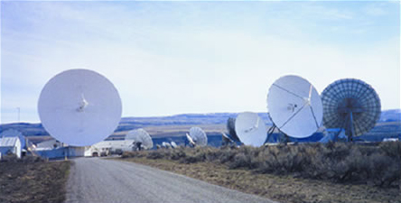 Figure 1. Verestar, Inc., a subsidiary of American Tower, Inc., operates several satellite communications facilities including the largest in the Western Hemisphere. Situated on 100 acres in Brewster, Washington, the site houses 40 operational antennas. The antennas, along with the site's electrical and communications/data systems, are bonded to an extensive copper grounding system based on four well casings, a 750-kcmil copper backbone and 4/0 ring-grounds surrounding each building. Ground resistance throughout the facility is less than 2 ohms.
Brewster is the largest of several satellite communications facilities owned by Verestar, Inc., now the largest teleport operator in North America. Verestar is a subsidiary of American Tower, Inc., a leading infrastructure provider for the wireless, Internet and broadcasting industries. Today, all but two of the dishes at Brewster are operational.
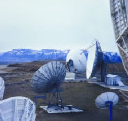 Figure 2. At the Brewster Earth Station, Verestar operates C-, C/L- and Ku-band antennas ranging in size from 3.5 to 30 meters. Some are fixed, but most are agile. All antennas are grounded either through their structures, through the sheath on the coaxial cable linking them to the communications facility, or both.
Among its other roles, Brewster also serves as a primary tracking station for communications satellite launches. In a typical operation, satellites might be launched from points as distant as Christmas Island and are tracked, simultaneously and in several languages, from Brewster, Kiev, Moscow and other locations around the globe.
Considering the $100 million-plus cost of commercial satellites, not to mention the value of the data they transmit, maintaining optimum signal quality and a high signal-to-noise ratio is absolutely crucial at Verestar. One of the most important factors leading to high S/N ratios is a properly designed and constructed grounding system, one that is free from ground loop currents and other spurious noise and above all one that provides a consistently low ground resistance.
Back to Top2-Ohm Grounding Resistance
Verestar understands the importance of good grounding, and the company gave it high priority as it expanded its operations at Brewster and elsewhere. When originally built as a COMSAT facility in 1965, the Brewster antenna farm was equipped with three primary grounding electrodes (in the form of drilled wells) that provided a grounding resistance of less than 2 ohms. Another electrode in the form of a 6-in (152-mm) X 100-foot (30.5-m) well casing was added in early 1999 as part of a system requested by a communications switch manufacturer.
Two ohms, maximum! Ground resistance that low is quite uncommon, even in many communications facilities. It is far lower than the 25 ohms cited as the maximum value for a single made electrode under the National Electrical Code (NEC), and it's comfortably within the 1- to 5-ohm range cited as being "generally suitable for large commercial installations" in IEEE Standard 142 (The Green Book).
Having a low ground resistance at the primary electrode system is important whenever a system contains sensitive electronic equipment. Equally important, however, is ensuring that the equipment sees that low resistance uniformly throughout the system. Uniform, low ground resistance minimizes noise caused by stray ground loop currents.
Back to Top"We use only copper"
To ensure uniformity, Verestar bases its grounding circuit on a network of heavy-gage copper conductors. At the circuit's core is a backbone constructed from bare 750-kcmil stranded bare copper cable (Figure 3). The buried backbone extends from the ring-ground surrounding the Communications Building to the ring-ground around the UPS building several hundred feet away and from there to the Operations Building. From the ring-grounds, bare stranded 1/0 and 4/0 conductors connect the individual building grounding electrode systems. In addition, a ground connection bonded to a 6-in (152-mm) X 100-ft (30.5-m) well casing connects to the comm building's grounding circuit, which in turn connects to the backbone. All grounding conductors, whether they are part of the backbone itself or located inside buildings, or at the antennas, exceed NEC minimum size requirements, sometimes by wide margins.
 Figure 3. A massive backbone of buried heavy-gage copper conductors connects all buildings and antenna structures at the Brewster site. Ring-grounds at all buildings are constructed from bare 750-kcmil copper, while 1/0 and 2/0 copper is used for star-grounds at antennas. All grounding conductors connect to a buried 750-kcmil bare copper backbone, which leads to the site's four main grounding electrodes, a series of deep well casings. The diagram shown here is representative, and many details have been left out for clarity.
Lupe De La Cerda, Verestar's chief electrical projects manager, installed most of the electrical and grounding systems at Brewster, as well as those at Verestar's other satellite facilities in Whittensville, Massachusetts, and Kingman, Arizona. "When I first became associated with Brewster, we knew the facility had a good grounding system because of its former defense-related missions," recalls Mr. De La Cerda. "Since then, we've added 39 antennas, and everything we've installed meets or exceeds the quality of the original grounding system. We use a lot of copper, about $100,000 worth of it on the Brewster site alone. In fact, we use only copper. You won't see any aluminum conductors here!
"And," added Mr. De La Cerda, "we know that ground resistance at Brewster hasn't deteriorated since 1965 because we check it periodically. We don't have to worry about corrosion. All buried connections are bonded exothermically. Above ground, we use either exothermic bonds (Figure 4) or solid bronze bolt-on connectors depending on the location and nature of the connection.
 Figure 4. An exothermic weld (bottom) bonds a 4/0 copper lightning down-conductor with 4/0 copper leading to the ring-ground buried around the communications building. The grounding conductors are also bonded to steel reinforcing rods in the concrete foundation and to the building steel above ground. The copper cable is only slightly tarnished, evidence of the acceptable corrosion conditions in Verestar's grounding conductor network. Further evidence that corrosion is not affecting the copper system is its continued low ground resistance, which has remained at 2 ohms since 1965.
In addition to its antennas, the Brewster site contains six buildings housing administrative offices, communications and mission-control facilities, transmitters and an uninterruptible power supply (UPS) that backs up the primary emergency power generator. The site actually has three generators, two of which are rated at 750 kW and one at 500 kW. The latest of the two 750 kW UPS units installed is shown in (Figure 5).The degree of importance Verestar places on reliability is evident in the fact that just one of the 750-kW generators alone is capable of carrying the entire site, should that be necessary.
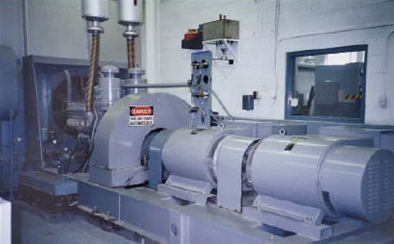 Figure 5. A 750-kW diesel-driven generator/UPS provides sufficient power to supply the entire Brewster facility in the event of an outage. A bare 4/0 copper grounding conductor connects the generator with the neutral-ground bond at the building's service entrance.
Grounding systems in the various buildings differ according to need, but all are linked to the 750-kcmil backbone. For example, one ground connection at the communications building is made at the 100-ft (30.5-m) deep well casing, which was installed specifically for the purpose. It leads directly to a home-runned subfloor grounding system (described below). That system is also connected to a halo ground in the building and to a buried 4/0 copper ring-ground surrounding the structure. The ring-ground is also connected to eight 20-ft x -in copper-clad supplementary electrodes located at each of the building's corners and midway along its exterior walls, and from there to the backbone.
Buildings are also fitted with air terminals (lightning rods) (Figure 6). Lightning doesn't pose a significant threat in Brewster's high desert environment, but it remains a valid concern. The site has experienced several lightning strikes over the years, but none of those strikes entered the transmitter, thanks to an effective protection system and the system's low-impedance ground. Air terminals on the communications building, for example, are connected by a loop of #29X lightning cable located on the roof. (Lightning cable is a braided, tinned copper conductor. The designation, "29X," identifies cable that is equivalent in cross-sectional area to 29 strands of #16 AWG wire.) Separate #29X conductors connect the rooftop loop to the building's tinned copper roof flashing. From there, 4/0 copper down-conductors connect to the ring-ground.
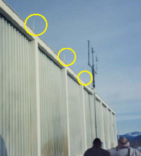 Figure 6. Air terminals provide lightning protection for the communications building at Verestar/Brewster. A rooftop ring constructed from #29X tinned copper lightning cable connects the terminals. Leads from the ring connect to the building's tinned copper flashing, and from there via 4/0 copper cable to a buried 4/0 copper ring ground surrounding the building. Eight 10-ft (3-m) deep copper-clad electrodes, one at the building's corners and one at each midwall point, are also bonded to the ring ground. The ring ground itself is bonded to the site's 750-kcmil copper grounding backbone, which connects all buildings and antennas to the four well casings that make up the primary grounding electrode system. One of the casings, installed at the request of a communications equipment supplier, is 100 ft (30.5 m) deep. The three-lobed device at center contains weather-sensing instruments.
Modified Subfloor Reference Grid
Inside the communications building, a 4/0 copper halo ground runs along the exterior walls, embedded in the concrete slab foundation. It is bonded to the building steel and to steel reinforcing rods in the slab (a form of Ufer ground). Additional 4/0 copper conductors extend from the halo ground to critical areas within the building.
The large communications room houses the site's telephone switch, which is equipped with its own UPS and battery plant, plus other communications gear and several mainframe computers. The room's extensive subfloor reference grid contains conductors laid out in both grid and star configurations (Figure 7). Chuck Fetty, Verestar's project manager, explains: "The room was originally equipped with a conventional copper reference grid under the raised floor. A portion of that grid is still in use, but the manufacturer of our telephone switch insisted that we modify the system for the switch according to their specifications.
 Figure 7. Schematic layout of the grounding conductors in the communications room. The supplier of Verestar's $2 million telephone switch specified a radial or "home-run" pattern of conductors for its equipment. Other equipment in the room is grounded via a copper subfloor grid. Both the grid and home-run conductors are bonded to the building's halo ground, and from there to the ring-ground, a deep-well grounding electrode and the facility's 750-kcmil copper back-bone conductor.
 Figure 8. A portion of the original subfloor reference grid in Verestar/Brewster's comm room. This portion, still in use, consists of a grid of 8-in x 1/8-in (200-mm x 3.2-mm) copper strips (center) interlaced with bare 4/0 copper cable. Equipment cabinets are bonded to the strips or cable. The grid itself is bonded to the halo ground surrounding the room, to the building steel and to the grounding electrode conductor entering the building from the exterior network. From there it connects to the backbone.
"In the original set-up, we ran a grid of 1/8-in (3.2-mm) thick by 8-in (200-mm) wide copper strips (Figure 8). The strips were connected with bare 4/0 copper, under the floor, to copper jumpers leading from the grid to each equipment cabinet (Figure 9a). The strips were (and still are) bonded to the grounding cable coming into the building. We continue to use the grid for some cabinets in the room; however, for the switch and its battery plant, plus some other equipment, we now home-run 4/0 copper from each equipment cabinet to copper collector plates, which are also located under the floor. These plates are connected, again using 4/0 copper, to a central collector plate (Figure 9b). The collector plate is connected to the new 100-foot (30.5-m) well casing with 750-kcmil cable. The three wells that made up the original grounding electrode system also join the new system at the collector plate.
Figure 9. Modifications to the sub-floor grid: (a) Grounding jumpers (#6-4/0 AWG green cables) connect copper ground buses in nearby equipment cabinets to a 6-in X 1/4-in (150-mm X 6.4- mm) collector plate. A 4/0 copper cable (black conductor at upper left) leads to a second collector plate, (b), along with four 4/0 cables from other plates. From here, a 750-kcmil conductor (right) connects to the room's halo ground and building steel and the exterior grounding network. A communications equipment supplier preferred this style of home-run connections to the existing reference grid. Verestar continues to use portions of the original grid for other equipment located in the comm room. The reference grid and home-run pattern are bonded at a common point leading to the exterior grounding network and its 750-kcmil copper backbone and to the new deep well electrode.
"We also installed -in x 2-in (6-mm x 50-mm) copper grounding buses inside most cabinets. The buses connect to individual pieces of equipment in the cabinets. For those connections, we use nothing lighter than #2 AWG, although we connect the buses with the subfloor collector plates with 4/0 copper. You have to remember that our equipment is very expensive; several of our cabinets contain as much as $200,000 in communications gear. The switch alone (Figure 10) is worth several million dollars. The cost of the copper grounding conductors is insignificant by comparison. "
 Figure 10. A portion of Verestar/Brewster's telephone switch. The switch and several related pieces of equipment are connected to a new home-run-style system of grounding conductors as well as to collector plates and an existing reference grid located beneath the raised floor.
Overhead Grounding Bus
In the operations building (Figure 11), a 4/0 stranded copper grounding conductor leading to the 750-kcmil backbone is bonded to the building steel and to an overhead bus constructed from 2-in x -in copper strip (Figure 12). Jumpers lead down from the strip to smaller copper grounding buses mounted inside the various transmitter cabinets and racks. Ground straps connect these buses to individual pieces of equipment.
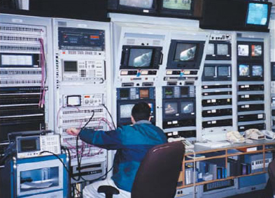 Figure 11. A portion of the interior of the operations building, where television and radio programming, as well as data, are relayed for broadcasters and communications clients worldwide. The extensive low resistance, copper-based grounding and wiring systems described in this article help protect the expensive equipment and ensure requisite high reliability.
 Figure 12. A grounding bus constructed from 2-in (50-mm) x -in (6-mm) copper strip runs overhead in Verestar's transmitter room. Jumpers extend down from this bus to the equipment racks, where further bus straps connect via jumpers to individual pieces of equipment. The overhead ground bus, which is in effect a partial halo ground, is bonded to a 4/0 copper ground conductor leading to the facility's 750- kcmil copper grounding backbone.
A bare copper ground jumper, one of several in Verestar's transmitter room, connects the overhead grounding bus to an equipment rack (Figure 13). All connections are bonded, ensuring that every piece of equipment maintains the same low ground potential. This practice minimizes ground loop currents, which could otherwise give rise to noisy signals and possible data transmission errors.
Buildings on the lower section of the site connect to star patterns of grounding electrodes surrounding the facility's 30-m antenna, which is also protected against lightning strikes by an unusual air terminal (Figure 14). The star patterns connect to the backbone leading to the site's ground wells.
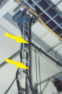 Figure 13. A bare copper ground jumper, one of several in Verestar's transmitter room, connects the overhead grounding bus to an equipment rack. All connections are bonded, ensuring that every piece of equipment maintains the same low ground potential. This practice minimizes ground loop currents, which could otherwise give rise to noisy signals and data transmission errors.
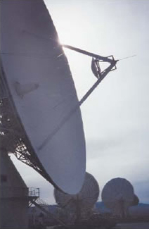 Figure 14. Unusual structures command unorthodox lightning protection. Here, an air terminal protrudes from the antenna support structure on Verestar's 30-m C-band dish. Lightning conductors, along with equipment grounding conductors, all connect to the site's 750-kcmil copper backbone.
The grounding connection in the main electrical room is made directly to the 750-kcmil backbone. As required by Code, the connection is at the ground-neutral bond at the service entrance. Grounds in subsidiary panels and auxiliary equipment are connected to the ground bus in the SE panel by way of 4/0 (or heavier) copper. More 4/0 copper is used for the ground connection to the feeder circuit from the emergency power generator.
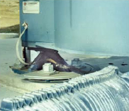 Figure 15. A flexible ground strap, left, connects a moveable antenna's structure to the Verestar 750-kcmil grounding backbone. The flexible strap is constructed of #29X tinned copper lightning cable. It is bonded to a 4/0 copper grounding electrode conductor (near bottom of photo), which leads to the backbone.
When ground potential differs at two or more points in a grounding system, the potential difference gives rise to a flow of current known as a ground loop. Since ground loop currents can contain frequencies extending into the RF range, they are a common source of interference in the form of background noise. Verestar/Brewster avoids such interference with its backbone and network grounding system. The uniform ground potential, plus careful attention to its electrical and communications system, enables the site to maintain the extremely low signal-to-noise ratio needed for satellite communications.
Back to TopFollowing Recommended Practice
Verestar follows other recommended practices for sensitive electronic equipment spelled out in IEEE Standard 1100. For example, the company installed separate dedicated branch circuits for computers, communications gear and other sensitive equipment. This practice produces several beneficial effects:
- Dedicating circuits for sensitive electronic equipment shields the equipment from voltage disturbances such as those resulting from switching on large electric motors;
- Dedicating circuits also helps shield sensitive equipment from harmonics generated in other circuits by such things as variable frequency drives, arc welding equipment and electronic fluorescent lighting ballasts;
- In addition, dedicating circuits also isolates high neutral currents generated by sensitive electronic equipment to those circuits. The switched-mode power supplies found in computers and other electronic equipment are rich sources of harmonics. By placing such equipment on dedicated circuits, the high neutral currents can be safely accommodated by simply oversizing or doubling the neutral conductor in those circuits. If necessary, harmonics can be trapped at or near the dedicated panel by use of appropriate filtering transformers.
Verestar also limits the number of outlets in its dedicated branch circuits. This practice further reduces the possibility that harmonics will accumulate to damaging levels. Finally, all sensitive circuits are equipped with isolated grounds (IG). IGs are not connected to the equipment grounding system; instead, they lead directly from each outlet to the ground-neutral bond at the service entrance. This practice helps avoid the noise caused by stray ground loop currents.
Proof of the value of the extensive grounding system at Verestar's Brewster facility can be found in the fact that the site has operated reliably and at the highest levels of signal quality for more than 45 years. As Mr. De La Cerda observes, "There are a lot of things that can go wrong in a facility as complex as this one at Brewster, but thanks to the system we have in place, grounding is something I don't have to worry about."
Back to TopThe Principals
Verestar, Inc. is a leading operator of full-service domestic and international satellite communications gateway hubs in the United States, transmitting a total of 3,450 Mbps of Internet, data, voice and video services worldwide. The company's customers include Tier-1 Internet service providers, data and voice carriers, television broadcasters and cable programmers. Verestar is a wholly owned subsidiary of American Tower Corporation. The company operates over 160 antennas at over ten U.S. locations in Arizona, California (Silicon Valley), Massachusetts, New Jersey, New York, Texas, Washington State and Washington, D.C.
 Chuck Fetty, Mr. Fetty is one of Verestar's project managers at the Brewster facility. He has worked at the site for more than two years. He monitors service projects and installation activities for Verestar. He has 15-plus years experience working at various satellite earth stations.
 Lupe De La Cerda, Mr. De La Cerda is chief electrical projects manager for Verestar. He joined the Brewster site in 1993 and is frequently called to other sites on power quality-related issues. Among his many duties, Mr. De La Cerda sees that national and state safety and electrical standards and codes are met during installation, thereby ensuring that the sites' sensitive equipment receives the highest quality of power at all times.