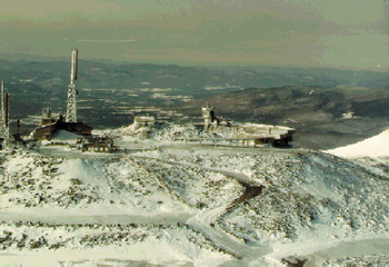
 Signals from the mountain's antennas reach an area covering much of northern New England. They carry not just TV and radio programming but countless telephone signals-ordinary phone calls as well as FAA air traffic control data, plus police, fire and emergency services. Because these signals affect millions of peoples' lives and property 24 hours a day, the communications center simply cannot afford any downtime.
Until 1993, all of the center's communications traffic, along with the millions of dollars in electronic equipment that makes it possible, were extremely vulnerable to such natural phenomena as snow- and wind-induced static discharges.
And lightning.
Two direct strikes per year would be about average on the mountain-more when the weather is especially bad. With each bolt, up to several hundred thousand amperes of current flows down whichever tower happens to be in its path to ground. That's enough energy to light up a small city, and it's certainly enough to fry the center's sensitive communications equipment.
Which it regularly did. Instead of taking a direct path to ground, lightning currents leaked to the center's equipment, causing about $140,000 in damage annually. Adding to the cost of ruined hardware was the lost airtime for the center's TV and radio tenants, and the disrupted telephone service and inconvenience to the public, not to mention the risks posed by interrupted emergency communications and FAA air traffic control.
The solution: better grounding
What was needed was a way to provide lightning strikes and other static discharges with a better path to ground so that their massive currents could safely bypass the communications equipment. The Mt. Washington towers were supposedly already protected against lightning, but the existing protection systems, installed years earlier, were hopelessly inadequate in that they lacked a good ground connection. Good, in terms of lightning and static-discharge protection, means low electrical resistance to ground; in Mt. Washington's case, it meant a maximum of 10 ohms 1 . The existing system indicated a resistance to ground greater than 1000 ohms!
Achieving low ground impedance took some doing, considering the mountain's 6000-plus feet of granite and permafrost. (The weather on Mt. Washington is so harsh that water-saturated rock below the surface remains frozen year-round.) It certainly required doing better than the existing system, which simply involved connecting all the towers with a large array of 10-ft (3-m) ground rods, the facility's water pipes and the rails of the mountain's cog-wheel railroad!
At the insistence of an equipment supplier, one of the mountain's primary communications tenants took steps to upgrade the quality of its grounding system. The company called in Ground Testing, Inc. (GTI), Billerica, Massachusetts. GTI has been designing and installing ground and lightning protection systems across the country since 1989.
After analyzing the existing protection system, GTI proposed that a set of deep grounding electrodes offered the only hope for a solution. It was a risky proposal on GTI's part. Their experience taught them that the proposed system should work, but no one knew if a good, low-resistance ground could be achieved in solid granite, much less granite infused with permafrost.
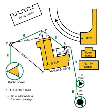 Figure 2. Sketch of site layout showing added electrodes. Each tower was surrounded by a 500 kcmil ring ground, exothermically welded to each leg.
To complete the installation, Burt Brooks, GTI's president, specified that all horizontal connections be exothermically welded and that all components of the system be connected using 500-kcmil copper cable. The cable is heavier than the minimum gage required by the NEC, but GTI saw the slight extra cost it entailed as cheap insurance.
Figure 2 shows the location of the two added electrodes (A), and their connection to the station master ground bus (M.G.B.). A 500 kcmil copper ring ground was installed around each tower and exothermically welded to each tower leg, then connected to the electrodes as shown. The master ground bus is a copper plate where the grounding electrodes of all the structures are electrically connected.
Results
GTI's experience paid off. The new system exceeded everyone's expectations. Resistance to ground was between eight and nine ohms, well within specification and orders of magnitude lower than the earlier system.
The Mt. Washington communications facility has never seen a major equipment loss or power outage due to lightning or any other discharge-induced cause in the five years since the new grounding system was installed. As an important added benefit, power quality at the site has improved measurably due to a much-reduced ground potential.
The new ground rods have maintained their low impedance. And, despite adverse weather and multiple freeze-thaw cycles, all of the copper connections have remained sound, with no evidence of loosening or corrosion.
Finally, the new protection system makes economic sense to the tower's tenants. Its installed cost was lower by far than the yearly cost to replace lightning-damaged equipment, let alone the loss of revenue due to power outages and signal interruptions. Without a doubt, Mt. Washington's investment in two boreholes, a pair of correctly installed copper-clad grounding electrodes and a few hundred meters of 500 kcmil copper cable has paid for itself many times over. Even more important, of course, is the improved reliability New England's communications customers now enjoy.
The Principals
 Burt Brooks is President of Ground Testing, Inc. Since 1989 the company has provided comprehensive earth resistance testing, as well as design services and installation of grounding electrode systems internationally. They are located at: 330 Boston Road, Billerica, MA 01862, and can be contacted at the following:
Phone: 978-670-8455
Fax: 978-670-8470
Email: [email protected]
Footnotes
-
 Maximum permissible ground resistance depends on several factors, including the type of equipment to be protected. The maximum resistance specified for the Mt. Washington facility was 10 ohms; other situations may require ground resistance as low as one or two ohms.