Performance of copper rotor motors compared to then produced standard efficiency aluminum rotor motors is presented in this section. Design to achieve EFF 1 efficiency levels was accomplished in large part by using electrical grade copper in the rotor rather than aluminum. Rotor conductor bar shape, stator lamination and winding designs were also modified in all but the smallest (1.1 kW) motor where copper was just substituted for the aluminum. The electrical steel was upgraded from a steel with losses of 8 W/kg to 4 W/kg in all of the subject motors. These modifications succeeded in raising efficiency over the entire load spectrum while at the same time maintained torque at critical points on the torque-load curve including starting torque. Table 1 presents the test data and performance characteristics of the four motors of this study. IEEE test method 112-B was used. Standard efficiency aluminum rotor motors are compared to the improved efficiency copper rotor motors. Copper rotor motors for use at both 50 and 60 Hz were designed, built and tested. The 50 Hz machines are described in this paper. Aluminum rotor versions of the higher efficiency motors were not built because the design study showed that the copper rotor approach would generaly result in lower size, weight and manufacturing costs.
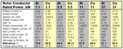
 Table 1. Test Data and Performance Characteristics of 1.1, 5.5, 11 & 37 kW Motors - Standard Efficiency Series Aluminum Rotor Models Compared to High Efficiency Copper Rotor Designs. 400 V, 50 Hz.
Efficiencies of the four motors are listed in the second last line. The values increase with rated power as expected and clearly meet or exceed the EFF1 targets. Other than the rotor conductor material, the 1.1 copper rotor motor differs from its lower efficiency aluminum counterpart only in the improved grade of electrical steel used. Substantially lower rotor and iron losses result. In contrast, the high efficiency 5.5, 11 and 37 kW motors have a completely new lamination and stator design. The design modifications relate to the starting behavior discussed below. The high efficiency copper rotor motors maintain the outer motor dimensions of the aluminum versions even with the design changes including a 20 mm increase in stack height.
Table 1 lists the losses by the five categories of the IEEE 112-B test for all four motors. It is clear that, in all but the small 1.1 kW motor, the main contribution to the reduction in losses arise from reduced rotor losses. The copper rotors show losses of about 50 to 60% of that of the aluminum standard rotor motors. The two copper rotor motors at the highest power ratings have an additional stack length of about 5%. If the effect of reduced electromagnetic utilization is taken into account, the reduction is quite considerable. Since lower losses also lead to the decreased operating temperatures shown in Table 1, stator copper losses are also reduced. Lower operating temperatures suggest that the copper rotor motors will require less maintenance and have longer lifetimes.
Stray load losses (SLL) become more important with increasing power ratings amounting to about 2% of input power at 37 kW. A trend which has often been observed is that copper rotor motors exhibit lower stray load losses. This can be explained by the fact that slip is lower as well as interbar currents are suppressed. Table 1 shows that at 50 Hz, the SLL are reduced in the copper rotors for the motors of this study. A factor influencing SLL is bar skew.
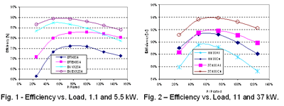
In industrial applications, it is quite common that drives do not run at full load at all times and partial load efficiencies must also be taken into account. Figures 1 and 2 show the dependence of efficiency on output power for the four motors at 50 Hz. Even in the partial load regime the efficiency of the copper rotor motors stays above the corresponding standard efficiency aluminum motors. Also the efficiency drop for output powers greater than 100% is smaller than it is for aluminum motors. This is due to the lower temperature rise of the high efficiency motor and therefore these motors have more thermal reserves which support good overload capabilities.

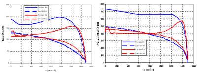
When aluminum bars are simply substituted by copper, as was the case for the 1.1 kW motor, the breakdown slip sk becomes lower since sk ~ R2. This approach leads to decreased starting torque and higher starting current. In Fig. 3a, torque-speed and current-speed curves for both 1.1 kW motors are compared. The starting torque of the copper motor is 15% below that of the aluminum motor but well above two times rated torque. On the other hand, starting current is increased by about 30%. But the absolute numbers are still controllable and far from being critical. For that reason only minor design changes had been necessary for 1.1 kW motors.
The situation is different for motors of higher power rating where starting currents become more and more critical. Therefore a completely new lamination design was developed for all SEW high efficiency motors above 3 kW. The curves in Figure 3(right) display the results for the 5.5-kW motor. Again the R2 effect with lower breakdown slip and steeper torque curves is obvious. But comparing the starting conditions, currents are nearly of the same magnitude, despite the lower rotor bar resistance. On the other hand the starting torque is approximately 20% lower but this was indeed a desired effect, since lower, but sufficient starting torque is beneficial for gear box life. Similar trends are seen in Figure 4 for the 11 and 37 kW motors.
As noted above, in taking the decision to use copper in the rotor for this series of industrial drive motors to reach EFF1 minimum efficiencies, SEW conducted an extensive modeling study comparing the size, weight and overall costs of motors of equivalent efficiency using aluminum in the rotor. The finding was that, for the motors discussed here, the use of copper in the rotor cage allowed reductions in rotor diameter, in iron required for laminations and in stator copper windings. The copper rotor motors are one frame size smaller than the the aluminum rotor design would have allowed. Overall there was an accompanying reduction in total manufacturing costs; the cost of the motor with an aluminum rotor at a given EFF1 efficiency ranged from similar to 15% higher than the copper version. In these examples, weight savings of up to 18% and cost savings of up to 15% were effected. This cost saving for the copper rotor motor was in spite of the die-casting component of the copper rotor being typically three times more costly than the aluminum rotor.
 Fig. 3 - Torque-speed and current-speed curves for the 1.1 kW motors (left) and 5.5 kW motors (right). Standard efficiency aluminum motor (blue); high efficiency copper motor (red).
 Fig. 4 - Torque-speed and current-speed curves for the 11 kW motors (left) and 37 kW motors (right). Standard efficiency aluminum motor (blue); high efficiency copper motor (red).