Designing a high efficiency motor requires that the designer focus on other aspects of motor performance besides efficiency. The customer also demands "reasonably shaped" torque-speed and current-speed curves. Starting conditions are especially important to project drive solutions.
For motors larger than 3 kW, SEW has adopted completely new designs for the copper high efficiency motors. This section exemplifies some of the design issues that have been investigated during the design process for a series of motors ranging from 15 kW up to 22 kW. An 18.5 kW motor is used here to illustrate the process for all the motors in the series.
One major point in the design of high efficiency motors is to reduce rotor resistance R2. In copper rotor motors this is obviously done by a much better conductivity of the cage material. However there are rotor design alternatives that allow for somewhat more cage cross sectional area which additionally helps to reduce R2. On the other hand rotor design also strongly influences the torque performance. Therefore these choices have to be carefully considered. For the motor series mentioned, two design concepts have been intensely analyzed. The first one consists of a stator with 48 slots and a rotor with 36 slots. The second one has essentially the same stator layout but with a 40-slot rotor. Fig. 1 shows the two layouts.
As a first rough assessment, the copper weight in the cage bars was compared.
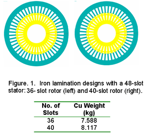
Using FEM calculations, the higher copper content in the case of the 40-slot rotor was arranged in such a way that the B-field peak values are comparable to those of the 36-slot rotor. As a result the calculated peak induction values in the rotor teeth are only 7 mT higher than for 36-slot rotor despite the 7 % increase in bar cross sectional area. Fig. 2 illustrates results from a FEM flux density calculation.
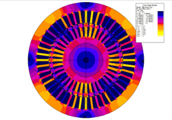 Fig. 2. Illustration of the results for a FEM flux density calculation for the 48/40 design.
Besides the influence on resistance the rotor slot number also has a strong implication for the harmonic distortion of the air gap field which again affects properties like torque performance, iron losses and stray load losses. Therefore the air gap induction along one pole pitch has been calculated for both design options by FEM. Fig. 3 displays the results for the combination of a 48-slot stator and 36-slot rotor and for the 48/40 combination.
A harmonic analysis has been performed for both Bgap(x) functions. The analysis showed that the 5th harmonic is expected to be somewhat smaller for the 36-slot rotor indicating a higher starting torque. However the total harmonic distortion of the air gap induction is significantly lower in the case of the 40-slot rotor. Actually the Bgap(x) total harmonic distortion (THD) for the 40-slot rotor is only 60 % of that of the 36-slot rotor.
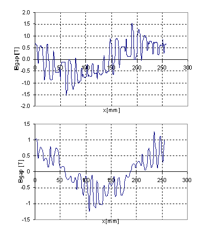 Fig. 3. Air gap induction along one pole pitch calculated for two design options for the copper rotor 18.5 kW motor. Top; 48/36 combination. Bottom; 48/40 combination.
Of course there is no strict and common relationship between harmonic content and stray load losses but generally a high harmonic distortion is always regarded as an indication of potentially high stray load losses. For that reason the 40- slot design should yield somewhat lower stray load losses.
Another point of interest for copper rotor motors is starting performance since the lower R2 leads to higher locked rotor current and reduced starting torque. Therefore the design of the starting cage is crucial. Fig. 4 shows the dependence of locked rotor current and torque as a function of the outer cage bar diameter for the 40-slot rotor design.
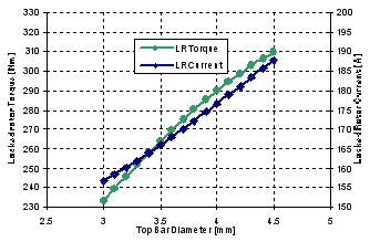 Fig. 4. Calculated starting current and torque as a function of the outer cage bar diameter for the 48/40 combination.
From that calculation an outer bar diameter of 3.5 mm has been determined as a good compromise between locked rotor torque and current.
For a complete performance evaluation, the efficiencies of both designs were calculated with the parameters and design options mentioned above for the 18.5 kW motor. The efficiency calculated for the 48/36 combination was 91.5%; that for the 48/40 combination was 91.7%. The 48/40 design has a slight advantage because of the lower stray load losses as well as the higher copper content.
Both rotor designs were built and tested according to IEEE Standard 112B as prototypes in the same 48-slot stator. Table I shows some of the basic results and the segregation of losses. It can be observed that the slip for the 40-slot rotor is smaller leading to lower Pcu2 losses. Also the stray load losses Psll are smaller for the 40-slot design. However the advantage is not as big as might be expected from the analysis of air gap harmonics, especially if the lower slip is taken into account. But as mentioned above, there is no hard correlation between harmonics and stray load losses. There are a number of other factors contributing to Psll such as interbar currents.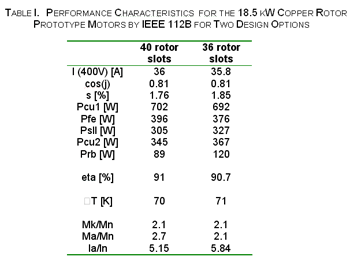
It is also obvious that the iron losses are different and higher in the case of the 40-slot rotor despite the lower harmonics. The reason is not yet clear. A potential explanation could be an erroneous segregation of friction and iron losses since the sum of both is nearly the same number. It should also be mentioned that the prototypes are measured in a gray cast iron housing which tends to increase the iron losses. This is also the reason why the iron losses for both designs are higher than expected and therefore the calculated efficiencies are higher than the measured values. The commercial series is equipped with die- cast aluminum housings consistent with the condition under which the calculations had been made.
