- Abstract
- 1. Introduction
- 2. Biofouling
- 3. Biofouling Resistance Of Cu-Ni Alloys
- 4. Application Of Cu-Ni For Prevention Of Biofouling
- 5. Conclusions
- References
ABSTRACT
The visible appearance of macro-organisms is only the last stage in development of biofouling and its development depends on many different factors. The marine growth effects strongly corrosion processes and operating parameters of marine engineering plants, thus it should be considered as an important design factor. The biofouling resistance of the UNS C70600 is attributed to the release of cuprous ions and the structure of the oxide film. Due to this attractive characteristic combined with a good corrosion resistance Cu-Ni components are considered as reliable and cost-effective alternative piping and cladding material in offshore and shipbuilding industry.
Back to Top1. INTRODUCTION
The service conditions in marine environments are known to be very aggressive to nearly all materials. Therefore, marine engineers have sought a cost-effective solution which can reliably be used for a diverse range of applications. The attractive characteristics of Cu-Ni alloys combine both corrosion- and biofouling resistance such that UNS C70600 (90-10 Cu-Ni, Cu-Ni) has been widely used in marine service for many decades. When compared with competing design materials for applications in seawater, the biofouling resistance of 90-10 Cu-Ni can be regarded as unique. This paper will provide a review of available literature sources related to the development and importance of marine biofouling. In addition, mechanisms and service experience for 90-10 Cu-Ni in applications involving biofouling prevention will be discussed.
Back to Top2. BIOFOULING
2.1 Development of Biofouling
Marine biofouling is generally defined as the establishment of a biological layer on the surface of solid matter which is exposed to seawater. It should be noted that the visible appearance of organisms such as barnacles, tubeworms, mussels etc. is only the last stage in development of biofouling (1) (Figure 1). As soon as a solid is in contact with seawater, organic matter will settle on the surface resulting in the establishment of a glycoprotein film. Marine bacteria, unicellular marine organisms, such as diatoms or filament algae, are normally the next species to appear on the material (2). The presence of the primary film presumably attracts bacteria by means of a supply of organic nutrients (3) or by providing a sufficiently protective environment (4).
 Figure 1. Biological sequence of the development of biofouling.
The diversity of organisms within the bacterial film act symbiotically and produce conditions that are desirable for growth of other bacteria or species. Species at the biofilm/solution interface are subjected to a high supply of oxygen and complex nutrients. Aerobic bacteria utilise the oxygen and break down the carbon sources producing simple polymers and fatty acids. The bacteria within the film use these waste products for metabolic processes (3). A layer of bacteria and unicellular organisms is a requirement for many macro-organisms, which colonise the surface by means of larvae, to settle providing them with an appropriate area for attachment (2).
Most minute organisms need sites where they can permanently attach themselves. This can be achieved by production of extracellular polymer substance (EPS) - a glue-like material - shortly after settlement. Other organisms, such as barnacles, generate calcareous matter that is deposited on a solid surface. It should be noted, that hard and smooth surfaces, such as glass or polished stainless steel, normally allow more secure attachment than soft materials. Non anti-fouling coatings are very susceptible to fast colonisation by biofouling (2) and can serve as a nutrient source for bacteria (4).
Back to Top2.2 Factors Influencing the Biofouling
The extent of marine growth depends on such factors as geographic location, season of the year, temperature, type of material, amount of light, and distance from the shoreline.
Whilst bacteria can be found nearly anywhere in the marine environment, the habitat of macro-biofouling organisms is often limited by depth. Some kinds of barnacles live at depths up to 60-70 m. Others exist only in the direct vicinity of the surface and are rarely found deeper than 1 m from the mean tide level (5). Most kinds of plants depend on a sufficient supply of light and thus only occur in surface water.
Under slow moving conditions, the larvae have no difficulty in attaching to the surface. The velocity limit cannot be exactly determined because of the importance of the surface finish and the shear stress on the surface imposed by a moving fluid. It has been reported, however, that bacteria and other organisms in the primary film might withstand high hydrodynamic regimes such as seawater flow rates of 1.8 m/s (6).
Back to Top2.3 Effects of Biofouling on Corrosion Processes
The biological film contributes to an alteration of surface energy and the electrochemical behaviour of metals is modified in the presence of metabolic products. The region beneath the film becomes anaerobic leading to the establishment of cells with differential aeration, and the development of anaerobic species such as sulphate-reducing bacteria can occur. The outward movement of metabolic products is impeded resulting in accumulation of these agents and leads to the establishment of concentration cells (7). Furthermore, a single organism may exert an influence on corrosion reactions by agents produced during its lifetime, or by products of decay even after its death.
Since, the structure and the functionality of the biofouling depend on many different factors, it is rather difficult to predict the effect of marine organisms on the corrosion process. However, it can be summarised as follows:
- Production of corrosive agents such as sulphides or acids
- Depolarisation of corrosion reactions
- Modification of the nature of corrosion products, oxidation or reduction of metallic ions
- Interaction with the environment (e.g. consumption of oxygen)
- Localised changes of water chemistry (e.g. pH, metal ion concentration)
- Localised coverage of the surface and promotion of galvanic interaction
2.4 Effect of Biofouling on Plant Operation
Biofouling not only effects corrosion processes but can also seriously influence the efficiency of marine engineering plant. The presence of biofouling in piping systems may lead to an increasing pressure drop, unacceptable reduction in flow, or even complete plugging. Furthermore, the presence of a biofouling film 250 µm thick may result in 50 % reduction in heat transfer of heat exchangers (10).
Although a certain level of biofouling on ship hulls is sometimes tolerated, it has been shown that a 1 % power increase is required for every increase of 10 µm in hull roughness (in the range of 0-230 µm) to maintain speed. Statistical evaluation of British ships revealed that the average roughness of a new hull is about 125 µm, and the average yearly roughness increase ranges from 50 to 70 µm. A conventional hull, therefore, starts to loose its efficiency from the day it is launched, whereas a Cu-Ni hull contributes to increased efficiency with time (8).
Weight increase of marine structures due to build up of biofouling is another critical issue. In addition, marine growth contributes to an increase in the structural roughness and dimensions leading to enhanced hydrodynamic interaction between the marine structure and wind, waves and currents. Marine growth becomes an important factor in design, operation and maintenance as it can lead to significant extra costs due to treatment of seawater with biocides and frequent cleaning of pipe work and outer structural surfaces.
Back to Top3. BIOFOULING RESISTANCE OF CU-NI ALLOYS
The question: "Is there an appropriate design material, which can prevent the development of biofouling?", can be answered positively. The high copper alloys - particularly the Cu-Ni alloy with 10 % nickel UNS C70600 - reveal a unique biofouling resistance, which can last throughout the service life in marine environments. Table 1 summarises the chemical compositions of the alloy specified by common international standards.
| Standard | DIN/EN | ASTM | ISO | EEMUA | KME |
|---|---|---|---|---|---|
| Designation | CuNi10Fe1Mn | CuNi10Fe1Mn | CuNi10Fe1,6Mn | ||
| Ref. No. | 2.0872/ CW352H | UNS C70600 | UNS 7060X | Osna10® | |
| Copper | Rem. | Rem. | Rem. | Rem. | Rem. |
| Nickel | 9.0-11.0 | 9.0-11.0 | 9.0-11.0 | 10.0-11.0 | 10.0-11.0 |
| Iron | 1.0-2.0 a | 1.0-1.8 | 1.0-2.0 | 1.5-2.00 | 1.50-1.8 |
| Manganese | 0.5-1.0 | 1.0 | 0.5-1.0 | 0.5-1.0 | 0.6-1.0 |
| Tin | 0.03 | - | 0.03 | - | 0.03 |
| Carbon | 0.05 | 0.05 c | 0.05 | 0.05 | 0.02 |
| Lead | 0.02 | 0.02 c | 0.02 | 0.01 | 0.01 |
| Phosphorus | 0.02 | 0.2 c | 0.02 c | 0.02 | 0.02 |
| Sulphur | 0.05 | 0.02 c | 0.02 c | 0.02 | 0.005 |
| Zinc | 0.05 | 0.5 c | 0.5 | 0.02 | 0.05 |
| Cobalt | 0.1 b | - | 0.05 b | - | 0.1 b |
| Total other impurities | 0.2 | - | 0.1 | 0.3 d | 0.02 |
| Single values represent the maximum content. a: for marine applications must be negotiated between supplier and customer b: the value has to be taken into account of Ni c: when required for welding d: impurities are elements other than copper (including silver), iron, nickel (including cobalt) and manganese |
|||||
In general, the natural corrosion process of copper alloys can be subdivided into primary and secondary reactions. During the primary reaction, a cuprous oxide film is formed. The anodic part of the reaction takes place at the metal/oxide interface and the cathodic part at the water/oxide interface (Figure 2). Since the cuprous oxide film does not represent a completely dense layer, the Cu-Ni continuously releases small amounts of copper ions. Because the ions cannot be tolerated by many organisms, such an ionic discharge is capable of decelerating the establishment of the primary bacterial film considerably. The required corrosion rate of 90-10 Cu-Ni is well below 25 µm/y, which is the usual corrosion rate of this alloy in marine environments (9). If Cu-Ni is cathodically protected, however, the biofouling resistance can be decreased.
 Figure 2. Corrosion reactions during formation of protective oxide layers on Cu-Ni.
The formation of slime film on titanium, copper and 90-10 Cu-Ni was studied after different exposure duration in coastal waters (10). Figure 3 shows that titanium is the most susceptible to slime formation, whereas the pure copper revealed the best resistance. The biofouling properties of Cu-Ni were intermediate between titanium and pure copper.
 Figure 3. Thickness of slime films on different materials exposed to stagnating seawater.
The release of toxic ions can lead to a reasonable question: "Can utilisation of 90-10 Cu-Ni cause an ecological impact?". This topic was extensively discussed as well (11). Having been released, the copper ions tend to generate organo-metallic complexes and become, therefore, biologically unavailable. It was concluded that, if Cu-Ni corrodes at normal corrosion rate, no detrimental ecological effects are expected.
Further, the secondary corrosion reactions also play an important role in biofouling resistance of the material (Figure 2). During this part of the corrosion process another oxide layer is generated by a reaction of released ions with compounds in seawater. This top layer consists usually of cuprous hydroxide or hydroxychloride and represents a thick and porous structure (12,13). Similar reactions can be developed for Fe and Ni - the main alloying elements. (14) Bacteria of certain genus, which are protected by a polysaccharide lining from the copper ions, were found within the oxide layers and attributed to the coverage of organisms by products of secondary corrosion reactions (Figure 4) (10).
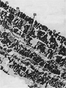 Figure 4. Transmission electron micrograph of bacterial layers sandwiched within corrosion products of Cu-Ni exposed in Langstone Harbour after 22 weeks B - bacteria between layers of corrosion products, S - no bacteria found on the surface (12,000:1)
The top layer can be regarded as a barrier for the diffusion of copper ions into the seawater, and the Cu-Ni surface may become susceptible to biofouling. Therefore, during initial stages of exposure, the biofouling resistance of copper is controlled by the release of copper ions. During the following exposure, a poorly adherent layer is formed on the top of a cuprous oxide layer and the surface may foul. However, the top layer can be easily removed and thus prevents the attachment of macro-organisms. The freshly exposed film remains intact and is resistant to biofouling (Figure 5) (15,16).
 Figure 5. a: Initial formation of protective Cu 2O film (establishment of fouling is prevented by release of cuprous ions), b:Establishment of non-toxic top layer, c: Settlement of the surface by fouling organisms, d: Removal of fouling organismsleaving the protective Cu 2O film intact.
The University of Applied Science, Hamburg, and KME conducted a series of exposure tests in three different environmental zones: splash, tidal, and submersed at Helgoland, in the North Sea (17). Figures 6a-c illustrate the appearance of Cu-Ni 90/10 samples after 2 years of exposure; Figure 6d shows for comparison carbon steel samples heavily covered with macro-fouling organisms after exposure for only one year at the same location. This example reveals clearly the advantage of Cu-Ni for biofouling prevention under marine conditions.
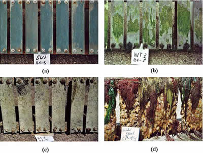 Figure 6. 90-10 Cu-Ni samples after 2 years exposure to different environmental zones at Helgo-land, North Sea: (a) Splash, (b) Tidal, (c) Submersed, (d) structural steel after 1 year of exposure at the same location under fully immersed condition.
4. APPLICATION OF CU-NI FOR PREVENTION OF BIOFOULING
4.1 Tubing Systems for Handling Seawater
The Cu-Ni alloys have been long recognised for their remarkable resistance to marine biofouling. Additionally, the following characteristics make the 90-10 Cu-Ni alloy the first material choice for seawater piping systems:
- Good corrosion resistance under quiet conditions
- Sufficient resistance to erosion-corrosion
- Cathodic protection is unnecessary
- Sufficient mechanical strength and good ductility
- Ease of fabrication
After 2.5 years of service on an 8-pile production platform in the Gulf of Mexico (18) , the steel intake and discharged headers were completely covered by an extensive hard shell layer. The inner diameter of 8-in. Schedule 80 pipe was reduced from 7 5/8-in. to approximately 5 1/2-in; the cross-section was reduced by 52 %. The thickness of biofouling inner cover was uniform within straight sections of the seawater line. However, it became thicker and richer in the discharge piping attributed to elevated temperatures and a decreasing concentration of chlorine. A short 28 in. section of the water intake prior to chlorination unit of the VERMELHO-2 ( PVM-2) platform, Brazil, is covered by a 10 cm thick biofouling layer within 45 days.
Such cases are well known from practical experience in the offshore and shipbuilding industries. Even slight biofouling increases the surface roughness leading to an elevated pressure drop. Figure 7 compares the roughness factors of Cu-Ni and steel piping depending on the service duration (19). Under optimal service conditions, the 90-10 Cu-Ni piping remains smooth during the whole service life due to the biofouling and corrosion resistance . The appearance of marine growth in the piping system often leads to a reduction in plant efficiency due to decreasing tube cross section. Sometimes this is compensated during design of the pipe work by means of over-sizing (18).
 Figure 7. Comparison of the pipe roughness between 90-10 Cu-Ni and structural steel.
The alternative involves costly chlorine treatment of seawater, which is known to significantly enhance the susceptibility of stainless steel to localised corrosion and to cause deleterious ecological impacts. Moreover, the concentration of the residual chlorine has to be kept to a certain level depending on the method of chlorine dosing otherwise the chlorine treatment of seawater may be insufficient and the marine growth can be difficult to control. In stand-by lines, such as fire-fighting systems, seawater chlorination is frequently problematical.
The biofouling behaviour of titanium and 90-10 Cu-Ni was studied at various velocities (20). The major fouling problem observed was the attachment of marine growth and silt particles at low velocities to the surface of titanium alloys. With increasing velocity the silt was washed away, however, the biofouling remained on the surface. The surface of 90-10 Cu-Ni "fouled" by corrosion products and silt at low velocities; but with increase of flow the surface became clean. It was concluded that non-cuprous systems always require an operating velocity in excess of 1 m/s.
Some researches discussed a fouling tendency of Cu-Ni. In a study related to the effect of the biofouling films on the heat transfer for various metals was demonstrated that cleaning periods of 90- to 100-day are required for copper alloy exchangers. For non-cuprous tubing, the 10-day cleaning period was necessary (21). Additionally, the corrosion rate of 90-10 Cu-Ni can be accelerated in the presence of sulphide-reducing bacteria.
System economics over the life of an offshore platform or a vessel consists of two significant parts: initial material costs and through life maintenance costs. Moreover, costs for chlorination systems and cathodic protection must be considered.
The maintenance costs for a 90-10 Cu-Ni system were estimated to be 25 % that for steel. In addition, the salvage value of Cu-Ni systems is rather high and is based on 25 % of initial material costs (18). Another very important item, which has to be included in the economic evaluation, is the revenue attributed to higher productivity and, due to lower production downtime resulting from less pipe maintenance. The long experience with Cu-Ni, which is known as a high reliability piping material, has proven itself during long service in many marine applications as the most cost-effective piping material.
Back to Top4.2 Cladding of Ship Hulls
The biofouling resistance of copper alloys for use as a cladding material for ship hulls has a long history. The technique was adopted by the British Naval and merchant fleets in the 18th century. Copper-alloy claddings have been successfully used on vessels giving the possibility to prevent increased surface roughness due to corrosion and marine biofouling leading to lower fuel consumption.
Nowadays, a lot of examples of successful uses of 90-10 Cu-Ni as cladding material are known (Table 2) (22). Until now, the utilisation of 90-10 Cu-Ni cladding has been restricted to small vessels with hulls completely of Cu-Ni plate or Cu-Ni clad steel plate. Figure 8 demonstrate the appearance of the Italian fire boat VF 541 "Sebatiano Bocchetto" prior to launching in the Adriatic and after 2.5 months in service.
| Vessel | Length (m) | Launched | Built | Hull Thickness (mm) | Operating |
|---|---|---|---|---|---|
| Asperida II | 16 | 1968 | Netherlands | 4 | USA |
| Ilona | 16 | 1968 | Netherlands | 4 | Curacao |
| Copper Mariner | 22 | 1971 | Mexico | 6 | Nicaragua |
| Pink Lotus/Pink Jasmine/Pink Rose/Pink Orchid | 17 | 1975 | Mexico | 4 | Sri Lanka |
| Copper Mariner II | 25 | 1977 | Mexico | 6+2* | Nicaragua |
| Sieglinde Marie | 21 | 1977 | UK | 6 | UK/Caribean |
| Pretty Penny | 10 | 1979 | UK | 3 | UK |
| Fireboat VF 541 | 21.5 | 1984 | Italy | 6+2* | Italy |
| 6+2*: 90-10 Cu-Ni clad steel plate | |||||
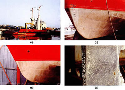 Figure 8: (a) Fire boat VF 541 launched in November 1984, (b) the Cu-Ni clad steel hull prior to launching, (c) the Cu-Ni clad steel hull after 2.5 months in service in Adriatic, (d) hard shell fouling on the coal tar epoxy coated propeller shaft after 2.5 months in the service in Adriatic.
Numerous successful test series have been conducted to verify the possibility of cladding container ships and chemical and oil tankers by cladding rudders and small areas on hulls. The severe test conditions ranged from the impacts and abrasion of Arctic ice, to tropical waters of the Panama Canal. The economical aspects were discussed in great detail as well (22,23).
When compared with tubing systems, where the maximum allowable velocity is about 3,5 m/s, the erosion-resistance of 90-10 Cu-Ni is sufficient even at velocities up to 12.5 m/s. The maximum thickness decrease was found to be 0.08 mm on the sheathed rudder of the Great Land (full power speed 24 knots) after 14 months in service (24). A hull roughness of approximately 20 µm was estimated, which is considerably different to the usual surface roughness of painted steel (210 µm) (22).
Back to Top4.3 Cladding of Offshore Structures
Whereas the sheathing of hulls on large vessels for biofouling and corrosion protection is a concept awaiting a definitive demonstration and testing, the application of sheathing on offshore units is well established (25,26).
An offshore platform is subjected to severe conditions, which lead to appreciable corrosion of most materials and a necessary corrosion allowance. In case of extensive marine growth, the allowable design stress of platform legs has to be increased due to accelerated dynamic effects of wind, waves and currents. The corrosion rate of steel in the splash zone can be 10 times higher than above and below this level. It is commonly attributed to high oxygen supply and abrasion by wave movement. The corrosion allowance prescribed by the certification authorities is about 12 mm for North Sea conditions increasing the weight and cost of platforms considerably. Additionally, a periodic inspection and cathodic protection often by means of heavy sacrificial anodes are mandatory because applied organic coatings are not reliable (27).
| Criteria | Mild (Malaysia) | Moderate (Gulf of Mexico) | Severe (North Sea) |
|---|---|---|---|
| Wave Height [m] | 10.4 | 21.6 | 27.4 |
| Storm Tide [m] | 2.4 | 1.5 | 2.7 |
| Wave Period [s] | 9.5 | 12.0 | 15.5 |
| Storm Current [m/s] | 0.0 | 0.0 | 0.5 |
| Wind Velocity [knots] | 89 | 113 | 97 |
| Material and Manufacturing Savings [%, Mill. US $ in 1984] | 4, 0.5 | 6, 0.6 | 9, 8.7 |
Using computer aided design, a recent evaluation reveals the potential cost savings if insulated Cu-Ni cladding is applied. (28) The potential savings result from reduced design requirements to withstand lower marine growth loadings, and, therefore, thinner material and easier fabrication (Table 3). Different scenarios: severe, moderate, and mild were considered in this study. It was demonstrated that greater reduction of costs can be achieved in deep waters and in areas with extensive marine growth. Figure 9 compares the potential savings per area sheathed for various environments and water depths. The reasons for the potential savings were attributed to four aspects:
- Installation time of offshore structures can be reduced. The 90-10 Cu-Ni-sheathing allows a decrease in the numbers of piles leading to installation of lighter structures. For instance, four days of installation in the North Sea amount to about US $ 1.2 million (1984).
- The reduction of corrosion attack on steel legs and cross members protected by Cu-Ni sheathing eliminates extra weight. The savings would result from the reduced material and the reduction of anode numbers needed to protect smaller areas of uncladded steel. Usually, the sacrificial or impressed current anodes are designed with large dimensions and suitable supports to last the expected life of the structure.
- Cupronickel cladding can result in lower stress in fatigue prone joints. Thus, the thickness of the joint can be reduced leading to decreased joint material costs.
- The reduction of stress applied by environmental factors contributes to a reduction or even elimination of the post-welded treatment applied of thick joints for stress-relief.
 Figure 9. The range of potential savings per area of sheathing for 1984 determined for various environments and water depths.
The costs for periodical removal of biofouling were not included in the calculations. However, costly cleaning procedures have to be conducted periodically and can cause costs of about 100.000 US $ per year under conditions in offshore California (1984). For more severe conditions in the North Sea, the savings due to elimination of cleaning on larger structures could be over ten times higher.
The complete cladding of an offshore structure would be an ideal solution. However, the non-destructive testing of fatigue prone joints that must be conducted periodically can be difficult. Otherwise, a removable cladding is needed to enable the detection of fatigue cracks (29).
For cladding/sheathing of steel, various methods are acceptable (27):
- Direct welding: 90-10 Cu-Ni pre-rolled sheet usually about 4 mm thick can be welded directly to the steel. In this case, organic coating of the uncladded steel must be applied to avoid galvanic corrosion of the steel and the deterioration of biofouling resistance of Cu-Ni.
- Welding on steel bands: To avoid the risk of copper penetration into structural members, steel bands 6 mm thick can be conventionally welded onto the offshore structure. The joints of the adjacent Cu-Ni sheathing coincide with the steel bands and are welded to them.
- Use of copper nickel roll clad onto steel plates.
- Insulated systems using epoxy or cement grout: Thick neoprene pads are mounted on the steel around the tubular steel. Over this a Cu-Ni shell is welded. Grout is pumped into the gap.
- Insulated system using the elastomer/Cu-Ni sheathing: The 1/4 in. thick butyl-base insulation adhesive/elastomer carries 1/16 in. 90-10 Cu-Ni sheet providing a bond, which is capable of withstanding the hammer driving forces during installation (29).
The choice of the sheathing technique depends on the particular application. If the whole structure can be sheathed, no cathodic protection of uncladded areas would be needed, no galvanic effects would be expected and the cheapest method would be direct welding. Full corrosion and biofouling resistance can be provided by insulated sheathing. The current approach is to cover the areas with most severe marine growth in splash and tidal zones using cathodic protection for lower parts. This technique would demonstrate the greatest economical benefit (28). Based on material requirements and field installation costs for sheathing platform legs, diagonals and conductors, the system based elastomer/Cu-Ni sheathing shows costs of approximately 19 US $ per sq ft (1985) (29).
Back to Top5. CONCLUSIONS
Marine growth is very complex and should be regarded as an important design consideration. The biofouling resistance of Cu-Ni is based on natural corrosion reactions and is attributed to the structure of the passive film.
The application of 90-10 Cu-Ni alloy in the offshore industry and shipbuilding is justified for both technical and economical reasons. Modern marine constructions are very costly, are designed for longer service life and are becoming larger and more complex. Cupronickel components are considered as reliable and cost-effective alternative piping and cladding material.
Back to TopREFERENCES
- Gershokov, S.M. and B. Sallman, Report of the Department of Microbiology, University of Miami School of Medicine, Miami, Florida, AD/A-045 815
- Clapp, W.F.: edited by Uhling, H.H.: The Corrosion Handbook, John Wiley & Sons, New York, 1948, 433
- ZoBell, C.E.: J. Bacteriol. 46 (1943) 39
- Little, B. et at: International Materials Reviews, 36 No. 6 (1991) 253
- Parvizi et al: International Materials Reviews, 33 No. 4 (1988) 169
- Berk, S.G. et al: Int. Biodeterioration Bull., 17 (1981) 29
- Little, B.: J. Coll. Interf. Sci., 180 No. 2 (1985) 331
- Peters, D.T.: "A Review of Copper-Nickel Alloy Sheathing of Ship Hulls and Offshore Structures", Publication of Copper Development Association.
- LaQue, F.A. and W.F. Clapp, Trans. Electrochem. Soc., 87 (1945) 103
- Blunn, G.W. and E.B.G. Jones, "The Immobilisation of Copper by Marine Fouling Microorganisms, " INCRA Project No. 332A, January 1984
- International Copper Association : The effect on aquatic environments of copper in colling water discharges from copper alloy condensers, New York, April 1998
- Liebert, B.E. et al: Corrosion, 21 No. 8 (1982) 22
- Kato, C. and H.W. Pickering; J. Electrochem. Soc., 131 No. 6 (1984) 1219
- Kievits, F.J. and F.P. Ijsseling: Werkstoffe und Korrosion, 23 No. 12 (1972) 1084
- Efird, K.D., Materials Performance, 15 No. 4 (1976) 16
- Videla, H.A. et al: Corrosion, 44 No. 7 (1988) 423
- Sass and Horn, University of Applied Science Hamburg, No. K241-2000, Hamburg, July, 2000
- Albaugh, E.K.; World Oil, November 1984, p. 94
- "Copper Nickel 90/10 and 70/30 Alloys - Technical Data", TN31, Copper Development Association, Sep. 1982.
- Ritter, R.B. and Suitor, J.W.: "Fouling Research on Copper and Its Alloys - Seawater Studies", INCRA Project No, 214A, Progress Report, April 1976
- Lewis, R.O.: Corrosion/82, Paper No. 54, NACE, Houston, TX, 1982
- Pricher, H. et al: "Use of Copper-Nickel Cladding on Ship and Boat Hulls", Copper Developments Association, Order No. TN 36
- Manzolillo, J.L. et at: "Copper Nickel Alloy Hulls - the Copper Mariner's Experience and Economics", Society of Naval Architectures & Marine Engineers Conference, New York, November, 1976
- Clathworthy, D.S.: Cladding the Sieglinde-Marie. Metal Constr., April 1979
- Moreton, B.B.: "Copper-Nickel Sheathing of Offshore Jacket Structures", Australian Corrosion Association Conference 26, Adelaide, Australia, November, 1986
- Kirk, W.W., "Metallic Sheathing of Protection of Steel in Seawater", Materials Performance, Vol. 26, No. 9, September 2987, p. 23
- "Copper-Nickel Cladding of Offshore Structures", Publication TN37, Copper Development Association"
- Barger, W.R. et al: "Economic Evaluation - Use of Copper-Nickel for Sheathing of Offshore Structures", INCRA Project No. 359, Final Report, 1984, International Copper Research Association
- Gaffoglio, C.J. : Offshore, November 1985, p. 59