by Arthur H. Tuthill, Brian Todd, and Dr. John Oldfield; Proceedings IDA World Congress on Desalination and Water Reuse; Volume I, Sessions 1 to 3; Paper No 73. Vol. III p251; October 6-9, 1997, International Desalination Association (IDA); Cencro de Estudios y Expertmerocion de Obras Pubiicas (CEDEX); Ministerio de Medio Ambiente; Ministerio de Formento; Madrid, Spain.
ABSTRACT
The first generation MSF desalination plants were built with copper alloy tubing and either bare or coated carbon steel chambers, water boxes and piping. The intended design life was 20 years. It soon became apparent that inleakage of air into the chambers allowed more corrosion of steel than could be tolerated. Steel in these applications began to be replaced with clad or solid copper alloy, and in some plants with clad or solid stainless steel. Currently many units use copper alloy throughout, although titanium tubing is used in some heat reject sections where sulfides or special considerations are overriding considerations.
Today the industry is building ever larger plants and extending design life to 40 years or more. This paper reviews the data and experience with copper alloy tubing, water boxes, piping and chamber walls in MSF desalination plants. These data summarize what has been learned through the past 30 years usage of copper alloys which have become the basic material of construction for both land based and marine MSF desalination plants. This information should provide the current generation of designers engineers with the data and performance history needed to obtain ever greater reliability from these key materials in the future than in the past.
NATURE OF COPPER NICKEL ALLOYS
The copper nickel alloys are solid solutions of copper and nickel with an iron addition which enhances their resistance to erosion and turbulence. The compositions of the three most widely used copper nickel alloys are given in Table 1. The C70600 alloy is used for piping, tubesheets, waterboxes, and flash chambers as well as tubing. In flash chambers and water boxes, it is used as a lining, as clad or solid alloy depending upon economics and local preferences. The C71500 alloy is used as tubesheets and tubing and in slightly modied form as the welding filler metal. The C76140 alloy is used as tubing. Mechanical properties are given in Table 2.
| Alloy | Nickel | Iron | Mn | Cu |
|---|---|---|---|---|
| C70600* | 9.0-11 | 1.0-1.8 | 1.0 Max | Remainder |
| C71500* | 29.0-33.0 | 0.4-1.0 | 1.0 Max | Remainder |
| C71640 | 29.0-32.0 | 1.7-2.3 | 1.5-2.5 | Remainder |
| *For welding the following Max % are allowed Zn 0.50, Pb 0.02, P 0.02, S 0.02, and C 0.05. | ||||
| TS | YS | ||||
|---|---|---|---|---|---|
| MPa | Ksi | MPa | Ksi | MPa | Ksi |
| C70600 | annealed | 275 | 40 | 105 | 15 |
| C70600 | light drawn (tube) | 310 | 45 | 240 | 35 |
| C71500 | annealed | 310 | 52 | 110 | 18 |
| C71640 | annealed | 435 | 63 | 170 | 25 |
| C71640 | drawn, stress relieved | 560 | 81 | 400 | 58 |
Although their good thermal conductivity gives copper nickel a decided advantage over ferrous alloys and titanium, the principal characteristic that has made copper nickel, the alloys of choice for marine heat exchanger applications, is their outstanding resistance to biofouling. No other competitive material can provide such good heat transfer with so little use of chlorine or other biocides.
Lewis demonstrated this characteristic of copper nickel by replicating typical condenser cleaning cycles needed to maintain heat transfer capability in clean seawater with normal biofoulers present.(1) He found that C70600 needed to be cleaned of rnicrofouling in about 110 days in order to maintain heat transfer capability, whereas a tube material with no inherent resistance to biofouling such as titanium would have to be cleaned 12 times in the same 110 day period to maintain equivalent heat transfer capability. Refer to Figure 1. This means, that if the use of chlorine were banned, or so reduced as to be ineffective, as many have advocated for environmental considerations, alloys without inherent resistance to biofouling would be at a serious disadvantage in the heat reject section. Lewis work also shows how dependent upon an adequate supply of chlorine are the alternative stainless steel and titanium tube materials.
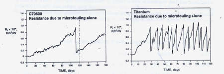 FIGURE 1. Time between cleanings to restore heat transfer due to microfouling in clean seawater (1).
WELDING
Although essentially solid solution alloys some precipitation of iron occurs in the C70600 alloy. The heat affected zone remains ductile and as strong as the base plate. Corrosion resistance is not significantly affected by iron precipitation when it occurs. These inherent characteristics allow good quality welds to be made by all of the normal welding methods with only routine welder training. The 30 % Ni filler metal is used to weld both the 30% nickel and the 10% nickel base metal in order to avoid shop and field mixup problems that could lead to welding the 30% nickel alloy with a 10% nickel filler metal. Mechanically such a weld would be satisfactory, however such a weld which is essentially a heterogeneous cast structure, would corrode very rapidly galvanically due to using a less noble filler metal.
CORROSION BEHAVIOR
The corrosion resistance of copper nickel alloys depends upon formation of a protective film. Film formation is referred to sometimes as "passivation". Film formation is affected by pH, time, aeration, velocity, temperature, pollution and other factors. There is generally an inner cuprous oxide film, Cu20, and an outer cupric oxide, CuO, film.(2,3,4) Although cuprous and cupric oxides are the principal components of the films, the lattice usually includes other metallic ions, iron, nickel, aluminum, calcium, sometimes silicon, and sometimes other species. Principal anions include chlorides, hydroxides and carbonates, bicarbonates and oxides. There is no fixed composition.
The inner film is normally reddish. The outer film may be greenish, brown or yellow-brown. Despite variations in composition, these oxide type films offer a high degree of protection, when formed under favorable conditions. In polluted waters, and in well water from shore side wells, the film is often a sulfide, rather than an oxide, type film. Sulfide films are readily distinguished by their black color. Sulfide films, while protective, are thicker, more porous and more easily damaged than oxide films.
 FIGURE 2. Formation rate of corrosion product film on Alloy C70600 in 60F(16) seawater.
Time is a major factor in film formation and also in the degree of protection the film affords. Figure 2 shows the rate of film formation on C70600 in 60F( 1 6C) seawater as measured by copper in the effluent.(5) In 10 minutes copper in the effluent decreased tenfold; in 2 hours a hundredfold, but it was 3 months before the film became "mature"; mature in the sense that copper in the effluent was only slightly more than copper in the intake water. Efird and Anderson's data in Figure 3 shows that corrosion rate, as measured by weight loss, continues to decrease in quiet and flowing seawater well beyond 3 months up to, at least, 7 years.(6) The fact that the film becomes more protective with time accounts for the considerable variation in corrosion rates and durability of copper base alloys as reported by different investigators in the published literature. Data obtained in short term tests, before a fully mature film has formed, can be expected to overstate the corrosion rate and to understate the durability of copper alloys.
 FIGURE 3. Corrosion rates for Alloy C70600 for long term seawater exposures.
Temperature has a major influence on the rate of film formation. At 60F(16C), Figure 2, it took slightly over one hour for the film to cover the surface and 3 months before a reasonably mature film reduced copper in the discharge close to the level of copper in the intake. At higher temperatures the film forms and matures faster. At lower temperatures, the film forms and matures more slowly. At 35F(2C) it took a week before a visible film completely covered specimens of C70600 in some work the author undertook. This corresponds roughly with the slightly over one hour it took for full coverage to occur at 60F(16C), Figure 2. Although the film forms more slowly at low temperatures, it does form and become protective, even in arctic and antarctic waters, as demonstrated by the good performance of copper alloy tubed desalination plants at Prudhoe Bay, Alaska, and McMurdo Sound, Antarctica. At 80F(27C), a common inlet temperature for MidEast desalination plants, rapid film formation and good protection can be expected within a few hours.
Oxygen is very important in film formation on copper alloys. Oxygen reduction is the primary cathodic reaction supporting corrosion, and film formation, of copper alloys in seawater. In the complete absence of oxygen, there would be no film formation and no corrosion of copper alloys in most waters. The feed from the heat reject section to the heat recovery section of many MSF desalination plants is deaerated, hence corrosion in the heat recovery section was not originally expected. However, the flash chambers of the heat recovery section are under vacuum and air is sucked in. In actual practice, there seems always to be sufficient oxygen present due to the residual oxygen content of heat recovery section feed and to in-leakage of air, to support some corrosion of copper alloys as well as substantial corrosion of carbon steel.
Another major factor influencing film formation is pH. Ross and Ross and Anderson (7,8) studied film formation on C70600, C71500 and C68700 in seawater and found no film formation below pH 6 even though there was adequate oxygen, 5.5-7.5 mg/l, present. The unfilmed corrosion rates were high, of the order of 35 mpy(0.89mm/yr.). At higher pH's, where some oxygen was present, corrosion rates were low and normal.
Velocity has several effects. At velocities below 3fps(O.9mps), sediment settles out readily in horizontal runs of pipe and tubing. Unless removed periodically, under-sediment corrosion, as evidenced by a general pitting attack, may occur. Slime layers also build up at low velocities providing a good habitat for biofouling organisms to attach to the slime layer and grow. At normal heat exchanger tube velocities, much of the biofouling is swept away because it is so lightly attached to the slime layer, which is one factor tending to keep the tubes clean and heat transfer capability in an acceptable range.
At normal design velocities of 5-8fps( 1 .5-2.4mps), turbulence around debris lodged in copper alloy tubes, partially blocking flow, has led to pinhole type failures of copper alloy tubing downstream of such lodgements. Efird studied the critical velocity at which the film is stripped away from copper alloys and the tube-wall-to-flowing seawater shear stresses that exist at the inlet end, 5 diameters down the tube, and around obstructions.(9) The critical velocity at which the protective film is stripped away by flow for the tube alloys is shown in Table 3. The tube-wall-to-flowing-seawater shear stresses are shown in Table 4. Efird developed these data on specimens placed parallel to the flow in the center of a one inch square cross section tube with clean sea water flowing on both sides of the specimens. The critical velocity for copper nickel is greater than the inlet end shear stress which confirms the better inlet end resistance of copper nickel as compared to other copper base alloy. The extreme turbulence that occurs around lodgements explain why pinhole type penetrations occur downstream of debris lodgements and underline the need for good screens and good screen maintenance.
| Critical Velocity | Temp | Critical Shear | |||
|---|---|---|---|---|---|
| Alloy | m/s | ft/s | °C | Stress, Mpa | |
| C12200 | (copper) | 1.3 | 4.4 | 17 | 9.6 |
| C68700 | (aluminum brass) | 2.2 | 7.3 | 12 | 19.2 |
| C70600 | (90/10 Cu/Ni) | 4.5 | 14.7 | 27 | 43.1 |
| C71500 | (70/30 Cu/Ni) | 4.1 | 13.5 | 12 | 47.9 |
| C72200 | (Cu-16Ni-0.5Cr) | 12.0 | 39.4 | 27 | 296.9 |
| Design Velocity | Tube Wall Shear Stress, Mpa | |||
|---|---|---|---|---|
| m/s | ft/s | Inlet | >5 L/D Down Tube | Around a 90% Blockage |
| 2.0 | 6.5 | 18.4 | 10.8 | 264.6 |
| 2.5 | 8.1 | 28.0 | <18.0 | |
| 2.75 | 9.0 | 33.0 | 20.0 | |
| 3.0 | 9.8 | 37.4 | 22.0 | |
SULFIDES
There have been a number of studies on the effect pollution and sulfides have on corrosion behaviors. There is considerable variation in these studies on the effect of sulfides and pollution. Syrett has published one of the better and most thorough studies on the effect of sulfides.(10)
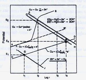 FIGURE 4. Influence of sulfide and oxygen on the corrosion current in a copper-nickel alloy exposed to flowing seawater.
Figure 4 from Syrett" s paper presents a large amount of useful information and is worth reviewing in some detail. The upper line AB represents the anodic reaction in aerated water and traces normal film formation. The initial section of line AB represents corrosion of unfilmed metal. The next, nearly vertical section, depicts the initial film forming stage where cuprous oxide is forming. The intersection with the oxygen reduction line, identifies the steady state corrosion current i2 at the normal potential, E2. The steady state corrosion current i2 corresponds to the steady state corrosion rate which is normally less than 25 microns per year for this copper alloy.
Line CD represents the anodic reaction in deaerated waters where sulfide is present. The cathodic reaction is hydrogen reduction line IJ; the corrosion potential is E1; and the steady state corrosion current is i1, point 1. The film that forms in fully deaerated, sulfide bearing waters is black, more porous, less adherent, and more easily damaged than the oxide type films previously described. The corrosion current is much lower, than in aerated waters, which would mean lower corrosion rates in sulfide infested waters, were it not for more porous, more easily damaged nature of the sulfide film. It should be noted that in deaerated waters in the absence of sulfides, hydrogen reduction does not occur, since copper will not displace hydrogen from water. It is only in deaerated sulfide bearing waters that the potential is depressed sufficiently for hydrogen reduction to occur.
When air is present in waters containing hydrogen sulfide, as can be the case with air in-leakage into the flash chambers which operate under a vacuum, the corrosion greatly accelerated. The intersection of the anodic line CD with the oxygen reduction line GH, point 2, identifies the condition where air and sulfides coexist in seawater. The corrosion current at point 3 is two orders of magnitude greater than i2, the corrosion current in normal aerated sea water, and, at least, three orders of magnitude greater than the i1, the corrosion current in deaerated sulfide bearing waters. Air and hydrogen sulfide do not coexist at equilibrium, as oxygen reacts with hydrogen sulfide to produce sulfur and water. However, there is abundant evidence that oxygen and hydrogen sulfide do coexist under transitory, non-equilibrium conditions. Corrosion can be quite severe when these conditions exist. For example, May and Weldon found that 3 ppm of H2S continuously added to clean aerated seawater increased the corrosion rate of these copper alloys 4 to 10 times. (11)
AMMONIA
Ammonia is sometimes encountered in the seawater feed to desalination plants. Ammonia may come from agricultural run off or from industrial plant discharges near desalination plant intakes. Ammonia affects different copper alloys differently. In the presence of air and ammonia, aluminum brass is subject to stress corrosion cracking. Aluminum bronze is more resistant and copper nickels are highly resistant to ammonia stress corrosion cracking as Thompson has shown, Table 5 (12). Ammonia also tends to increase the general corrosion rates of copper alloys. Quantitative data for the increase in corrosion rate due to ammonia contamination is not yet available. However, Figure 5 from Michels et al, shows the copper nickel alloys to be three orders of magnitude more resistant than aluminum brass, to general corrosion in spray and fog tests with 1000-2000 ppm ammonia present, a condition which can occur in the gas extraction zone of turbine condensers using hydroazine-type compounds for boiler water treatment.(13)
 FIGURE 5. Weight losses of various alloys after testing for 10 days in 1000 ppm NH3 contaminated condensate at 38C (100F). (13)
| Time to 50% | |
|---|---|
| Alloy | relaxation (h) |
| C44300 | 0.30 |
| C28000 | 0.35 |
| C46500 | 0.50 |
| C26000 | 0.51 |
| C68700 | 0.60 |
| C60600 | 4.08 |
| C61400 | 5.94 |
| C70600 | 234 |
| Cl4200 PDO copper | 312 |
| C71500 | 2000 |
CHLORINE
Chlorination practices vary considerably from site to site, as both the need for chlorination and local governmental regulations affect the amount actually used. The effect of chlorine residuals in the 0.5 to 3.0 ppm range on three tubing alloys is shown in Table 6.(14). The corrosion rate of C68700 is increased substantially by residual chlorine in the 0.5-3.0 ppm, C70600 is slightly increased and C7 1500 hardly at all. Francis found the principal effect the ranges normally used was to increase the susceptibility of copper nickel to impingement attacks.(15) Overdosing beyond 3ppm, which unfortunately occurs from time to time in a number of desalination plants, can be detrimental to performance of copper alloy tubing. Tubing in the heat reject stage is more likely to be affected by overdosing. Tubing in the heat recovery stage downstream of the heat reject stage, is less affected by overdosing, as the residual chlorine is consumed rapidly. Chlorine reacts rapidly with organic material and oxidizable species in seawater.
| Chlorine Residual | C68700 | C70600 | C71500 |
|---|---|---|---|
| 0.0 ppm | <1.0 (<0.03) | <1.0 (<0.03) | <1.0 (<0.03) |
| 0.5 ppm continuous |
2.9 (0.073) | 1.6 (0.04) | 0.4 (0.01) |
| 0.5 ppm 2hr on 2 hr off |
3.1 (0.08) | 0.7 (0.02) | - |
| 1.0 ppm 1 hr on, 5 hr off |
0.9 (0.023) | 3.2 (0.08) | 0.5 (0.013) |
| 1.5 ppm 2hr on, 2hr off |
0.9 (0.023) | 0.5 (0.013) | 0.1 (0.003) |
| 3.0 ppm 2 hr on, 2 hr off |
2.4 (0.06) | 0.3 (0.008) | 0.2 (0.005) |
SAND
Sand is common in seawater from open channels in shallow waters. High sand loadings can be detrimental to copper alloy tubing. Sato and Nagata have developed some useful guidelines on the effect of sand.(16). High sand loadings can damage the protective film, exposing bare metal to high unfllmed corrosion rates. For any given sand loading, damage increases with the size and sharpness of the sand present.
The general order of copper alloy resistance to sand follows.
1) C68700 - least resistance
2) C70600 - more resistant
3) C71500 - more resistant
4) C7 1640 - outstanding resistance
Sand is not always detrimental. Fine beach sands which are the most likely to be encountered are less damaging than larger angular particles encountered in some estuaries. Rough guidelines follow.
1) Up to 200 ppm of sand - Unlikely to be a problem
2)200-1000 ppm of sand - Increasing potential for damage. Good performance from the less resistant alloys has been reported after a mature film forms under favorable conditions.
3) >1000 ppm of sand - resistance of the first three alloys listed above is often inadequate. C7 1640 is usually resistant.
Intermittent exposure to even the higher loadings is not necessarily damaging, particularly when fully mature films have formed. Spikes are not as damaging as steady state loadings.
BRACKISH AND FRESH WATERS
Corrosion behavior in fresh, brackish and higher salinity waters is quite similar to performance in seawater. Experience indicates that velocity and turbulence damage may be a little less in brackish waters than in seawater, but there have been few studies made of velocity effects in fresh or low salinity brackish waters. Copper alloys seem to perform much the same in low as well as high chloride waters. It is the other factors discussed above, rather than chloride ion concentration, that appear to control performance.
DESALINATION ENVIRONMENTS
The principal desalination environments and their characteristics are shown in Table 7.
| # | Area and Environment | Chlorides ppm | pH | Temp °C |
O2 ppm | CO2 ppm |
|---|---|---|---|---|---|---|
| Tube-Side Environments | ||||||
| 1 | Seawater | 18,500-25,000 | 7.4-8.7 | 5-35 | 5-10 | 0.5 |
| 2 | Seawater from coastal wells with H2S or polluted seawater |
18,500-25,000 | 7.4-8.7 | 5-35 | <1 | 0.0 |
| Heat Recovery (HR) | ||||||
| 3 | Deaerated seawater, Stages 1 - 3 |
28,000-45,000 | 7.5-8.3 | 80-110 | <0.1 | to 2 |
| 4 | Deaerated seawater, Stages 4 - Last |
28,000-45,000 | 7.8-9.0 | 30-80 | <0.1 | to 2 |
| Brine Heater | ||||||
| 5 | 28,000-45,000 | 7.5-8.0 | 90-115 | <0.1 | to 2.5 | |
| Vapor - Side Environments | ||||||
| 6 | HR stages 1 - 3 | 1-20 | 5.0-6.0 | 85-110 | <1 | to 5+ |
| 7 | Vent condenser* | 1-20 | 5.5-6.5 | 30-110 | to 50 | to 100 |
| * The vent condenser may encounter up to 100 ppm H2S in plants where the water supply comes from shore side wells instead of open coastal waters | ||||||
Behavior in the two heat reject environments where, clean aerated or deaerated, sulfide seawater environments are encountered, 1 and 2 in Table 7 has been described above. One additional comment is needed to cover performance in the heat reject sections. This comment also applies to heat recovery and brine heater tubing. Earlier practice in acid dosed plants, involved dropping the pH to 3-4 with sulfuric acid additions for 24 hours or so to clean the tubes. This was a very effective cleaning operation, so effective in fact, that the protective passive film was removed to virgin metal, and had to be reformed after each acid cleaning. Metal loss for copper alloy tubing during film formation is of the order of 0.5 to 1 mil(0.025 mm). While no tube failures have been reported due to such acid cleaning, estimated corrosion rates from wall thickness loss as measured in eddy current testing have been reported, and give unrealistically high corrosion rate information. In such acid dosed plants, it would be more realistic to report the metal loss per acid cleaning, rather than as an elapsed time corrosion rate.
Behavior of copper alloy tubing in the heat recovery and brine heater sections was studied extensively in the Office of Saline Water desalination test facility at Dow Chemical Company's Freeport, Texas plant.(18) Figure 6 shows the flow diagram for this plant. Very careful and frequent measurements of the oxygen content, pH, temperature and other factors were made in this small scale desalination plant test facility.
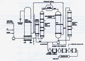 FIGURE 6. Flow Arrangement in Dow Chemical desalting plant.(18)
The seawater feed to the heat recovery section was clean seawater treated to remove oxygen to 3 ppb and CO2 to 1 ppm corresponding to the practice in acid dosed plants at that time. Oxygen content was adjusted and controlled to 75 ppb by adding oxygen saturated water. NaOH was added to adjust pH to 7.4. Inlet temperature was 1 1OF(43C). Oxygen was monitored carefully in the heat recovery section as shown in Figure 7. There was 30-75 ppb of oxygen in the heat recovery stages; enough to support corrosion of copper base alloys.
 FIGURE 7. Oxygen concentration and temperature
Instantaneous corrosion rates for these conditions over 30 months of operation are shown in Figure 8. The corrosion rate for C68700 alloy decreased from its high initial rate and leveled off at 3 mpy (0.075 mmpy) at 20 months. The corrosion rates for C70600, C71500 and C61300 were lower and still decreasing after 30 months. These data indicate that longer service life could be expected from C70600, C7 1500 and C6 1300, than from C68700, in the heat recovery section of the plant. These data support the widespread preference for C70600 alloy tubing in the heat recovery section.
 FIGURE 8. Instantaneous corrosion rates versus exposure time of five copper alloys in heat recovery section of test plant.(18)
Corrosion rates for C68700, C70600 and C7 1500 in the brine heater section, shown in Figure 9 were low, about 1 mpy (0.025 mmpy) after 54 months. Oxygen was measured and reported to be zero in the brine heater. However, the fact that there was some corrosion indicates enough oxygen must have been present to support the oxygen reduction reaction, even though it apparently was below the limit of detection.
 FIGURE 9. Metal loss (in mils) after 54 months of exposure in the brine heater.(18)
Corrosion rates in the recycling brine were even lower than in the brine heater, but still not zero as they theoretically should be in the complete absence of oxygen, as shown in Figure 10.
 [TDS 35,000ppm; Temperature 220F(104C); Oxygen 0 ppb]
FIGURE 10. Instantaneous corrosion rates (in mils per year) in the recycle brine exchanger.(18)
The effect of changes in the amount of oxygen present from 20 to 200 ppb on the corrosion rate of the three copper tube alloys was studied in a special side stream unit, not shown in Figure 6. The corrosion rate of C68700 was found to be more sensitive to changes in low concentrations of oxygen than C70600 and C71500, Figure 11. These data also support the widespread preference for 70600 as compared to C67800 alloy in the heat recovery section of current MSF plants.
 FIGURE 11. Corrosion rate vs. oxygen concentration
The feed to the heat recovery unit was unusually low in iron as nonmetallic materials were used for the piping and treatment plant. This allowed data to be developed on the effect of iron, as shown in Figure 12. The iron content was adjusted to 0.1 ppm by adding ferrous sulfate. There was a threefold reduction for the three copper alloy tube materials and a reduction of 50% for aluminum bronze in corrosion rate when 0.1 ppm Fe was added to the feed. This beneficial effect of soluble iron on the corrosion resistance of copper alloys in seawater has been reported frequently in the literature by other investigators. It is not surprising that it is also beneficial in the less aggressive heat recovery section environment.
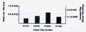 FIGURE 12. Effect of soluble iron on the metal loss in a Heat Recovery Exchanger after 5 months' exposure (averaged over eight passes). (18)
VAPOR SIDE CORROSION
While the effects of vapor side environments were not studied directly in the Dow Freeport program, the final report does state that unless C02 is effectively removed from the feed to the heat recovery section it will form low pH carbonic acid in the vapor zone and lead to increased vapor side corrosion (VSC). Vapor side corrosion of copper nickel tubing in the heat recovery section was not a significant problem in MSP plants until additives displaced acids for treatment.
In additive treated plants, CO2 is not removed in a decarbonator, as in acid treated plants. In additive treated plants, most of the CO2 is released in the first several stages downstream of the brine heater. The general approach has been to provide more or larger vents in the first three stages in order to remove the larger volume of CO2 released. In most cases a simple increase in the venting arrangements has been sufficient to prevent significant vapor side corrosion of copper nickel.
In a few cases, these venting arrangements have proven inadequate. As noted earlier and in the Dow report, should the pH drop low enough due to C02, corrosion of copper alloy would be expected provided sufficient air was also present. In the absence of air, CO2 even at low pH would not corrode copper nickel. In those units where vapor side corrosion has been reported, it appears to be greatest in the lower part of the cold end tube sheet. The film running down the inside of the cold end tube sheet apparently allows enough subcooling for the pH to drop sufficiently for corrosion to occur if there is sufficient air present. As the film runs down the inside of the tube sheet, the driving force to vent the incondensibles decreases allowing a "bubble of incondensibles" to form and persist in the lower part of the tube bundle at the cold end tube sheet. In those units where this has occurred, it has been found necessary to increase the driving force for removal of noncondensibles by inserting baffles, moving the vent closer to the lower part of the cold end tube sheet, enlarging the vent nearer the cold end tube sheet. The limited number of plants encountering significant VSC indicate that most units have adequate venting systems, or are so well maintained that the inleakage of air is insufficient to support significant vapor side corrosion.
The vent condenser is designed to condense the vapors vented from the steam side of the heat recovery section. Although these vapors are largely steam, they also contain CO2, oxygen, H2S if present, and other non-condensibles. Some vent condensers initially were installed with copper alloy tubes as the cooling medium was seawater. Rather severe vapor side corrosion occurred due to the high concentrations of CO2 and, when present H2S in the condensing vapors. The use of copper alloys in vent condensers was discontinued in favor of titanium and 6% Mo austemtic stainless steel tubing which are resistant to CO2 and H2S
EXPERIENCE WITH COPPER ALLOYS IN DESALINATION PLANTS
Three detailed surveys of materials performance in desalination plants were made by A. D. Little in 1968, 1972 and 198l.(19,20,21) Polyphosphate and acid were the two treatments in use at the time. These treatments have been largely superseded by the use of anti-scale additives, such as Belgard2000, which permit higher brine heater outlet temperatures and greater efficiency. Despite the change in treatment, the survey data still provides useful information. The three sections of MSF desalination plants are shown in Figure 13 to assist the reader in identifying the different sections in the following tables.
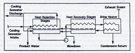 FIGURE 13. Block flow diagram of a desalting plant.(19)
Two major alterations in the tube corrosion environment occurred with the change to anti-scale treatment. First, the addition of acid during operation and running for long periods at low pHs, as was the practice in a number of acid dosed plants, was discontinued. With introduction of additives acid cleaning at low pH because a separate operation performed for a short period with better control of pH while the plant was off line for cleaning. The change to anti-scale additives in lieu of acid treatment reduced the metal losses from extended acid cleaning at low pHs, and increased the service life of copper alloy tubing.
Second, there was a change in carbon dioxide release. Carbon dioxide was vented off in the decarbonator in acid treated plants and was not a significant factor in the heat recovery section. In anti-scale additive plants, carbon dioxide remains in the brine until the brine reaches the first flash chamber downstream of the brine heater and may lead to VSC as just discussed.
Data on comparative usage and performance of copper alloy tubing is presented in the following tables. It should be kept in mind that these data include performance in many of the older acid treated plants. As explained above, even better service can be expected in modern anti-scale additive treated plants.
Table 9 reports tubing materials selection for first generation desalination plants. Tube selection for these early plants was based on performance of tubing in coastal power plants and marine condensers.
| Tube alloy | Heat Reject | Heat Recovery | Brine Heater |
|---|---|---|---|
| C68700 (Al Brass) | 23 | 68 | 22 |
| C70600 (90-10 CuNi) | 34 | 24.5 | 49 |
| C71500 (70-30 CuNi) | 1.5 | 1 | 1.5 |
| C76140 (70-30 CuNi 2Fe-2Mn) | 39.5 | 6 | 31 |
By 1976 tube preferences could be based on actual desalination plant experience as well as on
projections from coastal power plant and shipboard condenser experience. Tube preferences in 1976 were analyzed by recording tube selection preferences in actual bids, as reported in Table 1O.(22)
| Tube alloy | Heat Reject | Heat Recovery | Brine Heater |
|---|---|---|---|
| C68700 (Al Brass) | 6 | 46 | 0 |
| C70600 (90-10 CuNi) | 63 | 50 | 67 |
| C76140 (70-30 CuNi 2Fe-2Mn) | 27 | 3 | 33 |
| Titanium | 4 | 1 | 0 |
Materials selection for these 75 plants reflected the early preferences, as reported in Table 9, tempered by some ten years of actual desalination plant operating experience. The principal differences are the dramatic increase in use of C70600 tubing; the equally dramatic decrease in use of C68700; the major increase in use of C71640 in the heat reject section and the brine heater; and the near phasing out of use of C71500 tubing.
The increase in the use of C71640 in the heat reject section reflects its excellent resistance to erosion-corrosion as well as to sand abrasion in the shallow waters of the Middle East Gulf where sand loading can be high. These properties of C76140 tubing are reflected in the very low failure rates in the heat reject sections as reported in Table 11 below.
The marked increase in the use of C70600 alloy and the decrease in use of C68700 in the large heat recovery section reflects actual experience with the two alloys. Tube failure rates from the 1972 survey by A. D. Little, reported in Table 11 below, show much lower failure rates for C70600 than C68700, especially in plants using acid treatment.
| Tube alloy | Heat Reject | Heat Recovery | Brine Heater | |||
|---|---|---|---|---|---|---|
| Treatment | Polyphosphate | Acid | Polyphosphate | Acid | Polyphosphate | Acid |
| C68700 Al Brass | 7.2 | 17.7 | 0.18 | 9.0 | 5.6 | 49 |
| C70600 90-10 | 2.3 | 2.5 | 0.6 | 0.36 | 0.01 | 4.2 |
| C76140 70-30 2Fe-2Mn | 0.02 | 0.17 | 0.025 | - | 1.57 | 0 |
Tube failure rate was calculated by counting the number of tubes plugged as a percent of total tubes. this method of calculating "tube failure rate' overstates the actual tube failure rate by a factor of 5x or more because of the common practice of plugging six to eight "guard" tubes around each leaking tube.
These data indicate much better performance for C70600 than C68700. In the heat recovery section, much of the C70600 tubing was 20 gage, 0.035"(0.9mm), as compared to 18 gage, 0.047"( 1.2mm) wall thickness for C68700. Even with a thinner wall, performance of C70600 was significantly better than the heavier-walled C68700, in the plants using acid treatment.
While performance in the heat reject and heat recovery section is believed to reflect alloy capability in these environments, performance in the brine heater may not. Many tube failures in the brine heater are due to mechanical, rather than corrosion factors. When the brine heater scales up, it is necessary to ream out the tubes. The reaming operation not only removes scale but also metal from the wall, sometimes so much metal that the wall is penetrated in the reaming operation.
The higher tube failure rates in the acid treated plants are believed due to two factors: first, removal and reformation of the film with each acid cleaning; and second, unintended extensions of the time at low pHs, when there is no protective film and high corrosion rates.
There have been no major surveys of material performance in plants using high temperature additives. The literature and the author's experience indicate that usage of C70600 tubing has continued to grow relative to C68700. C70600 has performed exceedingly well in the large heat recovery section, except in a few plants where inadequate venting of CO2 in the first stage has led to high copper in the distillate readings and external corrosion failures of a few tubes. Brine heater tubing has performed well and there has been little change in alloy selection in this stage. Titanium usage has increased in the heat reject section and C70600 usage has decreased. This is believed due to titanium's better resistance to debris, partial blockage, and turbulence, which continue to cause failures of C70600, especially in units where screens are not well maintained. C71640 has held its share and continues to perform well in the heat reject section.
C70600 copper nickel welded piping and solid, clad and sheet lined waterboxes were originally used in the higher temperature heat recovery stages and the brine heater. Usage has expanded to include the full heat recovery section. C70600 tube sheets have been standard throughout the heat recovery section. C71500 tubesheets are used with C71640 tubing. The authors have not encountered problems with copper nickel piping, waterboxes or tubesheets. Performance has been excellent.
Based on 30 years of actual desalination plant experience, and the data developed in industry test programs summarized above, the copper nickel alloys can be expected to give even better service in the future than in the past.
REFERENCES
- Lewis, R. 0., "the Influence of Biofouling Countermeasures on Corrosion of Heat Exchanger Materials in Seawater", MP, Vol.21, Sept. 1982, pp 3 1-38
- North, R. F., M. J. Pryor, Corros. Sci., Vol 10, p197, 1970
- Gilbert, P. T., "A Review of Recent Work on Corrosion Behavior of Copper Alloys in Sea Water", MP Feb., 1982, pp 47-53
- Pourbaix, M., "Atlas of Electrochemical Equilbria in Aqueous Solutions", NACE, Houston, TX, 1974
- Tuthill, A. H., "Guidelines for the use of copper alloys in seawater", MP, Vol 26, No. 9ppl2-
22 1987 - "Corrosion Resistance of Wrought 90-10 Copper-Nickel-Iron Alloy in Marine Environments", INCO TP A-1222, 1975
- Ross, W. R., "The effect of seawater composition on corrosion of Cu-Ni-Fe alloys at elevated tempertaures", Corrosion/77, Paper No. 94, San Francisco, March 1977.
- Ross, W. R. and Anderson, D. B., "Hot Sea Water Corrosion of Copper-Base Alloys" MP Sept. 1975, pp 27-32
- Efird, K. D., "Corrosion/75 Paper No. 54, NACE, Houston, TX 1975.
- Syrett, B. C., "Sulfide Attack in Steam Surface Condensers", "Proceedings of Second Intl. Conference on Environmental Degradation of Engineering Materials in an Aggressive Environment" 1981 pp 3-14
- May, T. P. and Weldon, B. A., "Copper-nickel alloys for service in seawater", 24th International Congress on Fouling and Marine Corrosion, Cannes, France, 1964.
- Thompson, D. H., "Materials Research Std., Vol 1, p 108, 1961
- Michels, H. T., "The Influence of Corrosion and Fouling on Steam Condenser Performance", J. Materials for Energy Systems, Vol. 1, Dec. 1979
- Anderson, D. B., "Chlorination of Sea Water-Effects on Fouling and Corrosion", 1. of Engineering for Power, July, 1966
- Francis, R., "The effect of chlorine additions to cooling water on corrosion of copper alloy condenser tubing," Materials Performance, August, 1982, Vol. 21(8)
- Sato, S. and Nagata, K., "Factors affecting corrosion of condenser tubes of copper alloys and titanium" Corrosion 77, NACE, Toronto, 1977
- Hornburg, C. D., "Materials in desalination plants nickel alloys predominate," Desalination Water Reuse Vol. 3/3 pp. 33-40
- George, P. F., "Copper Alloys in the Desalting Environment" November, 1970 through November, 1973, Dow Chemical Company, Texas Division, Freeport Texas, for the Copper Development Association, 260 Madison Ave. NY, NY 10016
- Newton, E. H. and Birkett, J. D., "Survey of Materials Behavior in Multi-Stage Flash Distillation Plants", A. D. Little Inc., Cambridge, MA, August, 1968
- Newton, E. H., Birkett, J. D. and Ketteringham, J. M., A. D. Little Inc., Cambridge, MA, March, 1972
- Birkett, J. D. and Newton, E. H. "Survey of Service Behavior of Large Evaporative Desalting Plants", A. D. Little Inc., Cambridge, Ma, April 1981
- Todd, B., Private Communication, 1976
APPENDIX
Welding and Effect on Welding on Corrosion Behavior
Copper nickel, aluminum bronze and nickel aluminum bronze are easily welded by all of the common welding processes: manual metal arc, TLG, MIG, shorting arc-MIG, and pulsed arc-MIG. General features of these procedures are summarized in Table 1.(1,2) The copper nickels do not undergo significant phase transformations during welding. There is no grain refinement, rather grain growth and slight softening; i.e. there is an increase in ductility, not a decrease, as when welding carbon and low alloy steels. C61300 and C61400 aluminum bronzes are single phase alloys. C61300 has a 0.5% Sn addition to provide better resistance to stress corrosion cracking in high pressure steam, but in other services these two alloys are similar in corrosion behavior. C63000 nickel aluminum bronze is a two phase alloy. Its corrosion behavior varies with changes in composition within the ranges allowed by the specifications, and with heat treatment and the rate of cooling. A final heat treatment, 675C for 6 hours and air cool after welded fabrication, provides marked improvement to dealuminification and stress cracking.
There are certain elements, such as Pb, Te, Cd, 5, Sb, and Bi, which, if present even in small quantities in copper alloy base metal, promote hot shortness and cracking in the heat affected zone and in the weld deposit. ASTM A 171, "Copper alloy plate and sheet for pressure vessels, condensers and heat exchangers," allows higher than desirable limits for the undesirable elements, unless the procurement documents specify that the material is for welded applications. Good welding begins with specifying that the "material is for welded fabrication," as an addendum to the ASTM specification to which the material is ordered.
It is equally important to thoroughly clean the surfaces to be welded. Oil films, finger prints, and other organic films must be completely removed, as well as any tarnish films that may have developed from superficial atmospheric corrosion. Contaminants on the surface generally lead to porosity or cracking, or both, during welding.
Selection of the filler metal is important. Both copper nickel alloys are normally welded with 70-30 copper nickel filler metals, AWS ECuNi and ERCuNi. These 30% nickel filler metals are recommended for welding both the 10 and 30% Ni copper nickels. Welding both with the 30% Ni filler metals prevents the possibility of welding the higher nickel content alloy with a lower nickel content filler metal. If the higher nickel content alloy were welded with a lower nickel content alloy, the weld would corrode rapidly in seawater due to both the adverse galvanic effect and the unfavorable anode-cathode area ratio.(1)
Selection of the filler metal for welding aluminum bronze is also important. The proper filler metal for welding the 8% aluminum bronzes, C6 1300 and C6 1400, is not a matching composition material, but higher aluminum content filler metals, AWS ECuA 1-B and ERCuA 1 -A2 or -A3, in order to avoid heat affected zone and weld metal cracking. Unlike the copper nickels where the higher nickel content alloys are cathodic to the lower nickel content alloys, in the aluminum bronze family, the higher aluminum content filler metals are anodic to the lower aluminum content alloys. Therefore, in seawater applications, the final pass is often made with the 8% aluminum filler metals, AWS ECuA 1 or ERCuA 1-Al, to prevent preferential corrosion of the weld. In the heat recovery section, the low oxygen content markedly reduces galvanic corrosion. Changing to a matching composition filler metal for the final pass might not be necessary in heat recovery section waterbox and piping applications. (3)
In the early desalination plants, it was found that carbon steel waterboxes and chamber walls suffered more severe corrosion than anticipated in the deaerated brine. It became necessary to line steel waterboxes and chamber walls with either stainless steel or copper nickel. A MIG spot welding technique was developed for attaching C70600 copper nickel to steel that has been quite successful. (4) This is illustrated in Figure 14. Typical conditions for making the MIG spot welds in a 1.2 mm thick C70600 sheet are shown in Table 8. Details of the technique are reported by Ridgeway and Heath. (4)
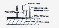
(a)
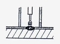
(b)
| Pitch of spot welds | 100mm |
|---|---|
| Effective diameter of spot welds | 4.8 mm |
| Voltage | 28V |
| Current | 240A |
| Contact tip distance from work-face | 12.5 mm |
| Filler wire type | 7OCu-3ONi |
| Filler wire diameter | 0.8 mm |
| Wire sun-in speed | 0.92 m/min |
| Wire speed-welding | 19 m/min |
| Welding time | 1.2 sec |
| Crater fill time | 0.12 sec |
| Argon flow rate | 1.6 m3/h |
Weld overlaid steel flanges are normally used in copper nickel piping systems. Figure 15 shows details of the overlay sequence. It is standard practice to use nickel copper filler metals, AWS ENiCu-7 and ERNiCu-7, for the first pass, as the iron dilution in the first pass is frequently high enough to crack C71500 unless special precautions are taken. The second and third passes are made with C71500 filler metals, AWS ECUNi and ERCuNi. Typical iron dilution and other details for a three-pass overlay are shown in Table 13. Nickel copper filler metals, AWS ENiCu, are also used for the copper nickel to steel welds on the outside of the pipe spool, as shown in Figure 15.
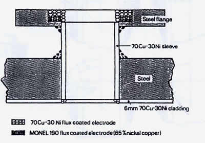 FIGURE 15. Suggested materials for manual-metal-arc welded flanged openings in 70-30 copper-nickel-clad waterbox of seawater condensers. (1)
Copper nickel tube-to-tube-sheet welds are sometimes used to seal the tube-to-tube-sheet joint in order to reduce weepage and rerolling. Figure 16 shows several preparations for making tube-to-tube-sheet welds. The (e) preparaiton allows the seal weld to be made between similar thicknesses and is preferred. Tube-to-tube-sheet seal welds are normally made automatically, and autogenously, under a good inert gas blanket.
| Electrode | Electrode diameter(mm) | DC current range (amp) | Deposit | Analysis |
|---|---|---|---|---|
| Layer | Total iron content per cent | |||
| 65% Ni-Cu (MONEL* 190) | 3 | 70-100 | 1 | 24.6 |
| 7OCu-3ONi (Monel 187) | 4 | 90-150 | 2 | 8.5 |
| 7OCu-3ONi (Monel 187) | 5 | 150-190 | 3 | 3.5 |
| *Trademark | ||||
 FIGURE 16. Tube-plate preparations employed with copper-nickel tube-to-tube-plate welded joints.(1)
Appendix References
- "Guide to the welding of copper-nickel alloys", INCO Europe Ltd. 1979.
- "Welding Handbook" Copper Development Association US from Chapter 68 Sxith Edition of Vol. 4 "Welding Handbook' AWS 1972.
- "Aluminum Bronze Alloys Corrosion Resistance Guide" Copper Development Association UK.
- Ridgeway, W. F. and Heath, D. J. "Lining mild steel components with 90/10 copper nickel alloy sheet" Welding and Metal Fabrication, October 1969, Inco London Publication 4210.
| Welding process | Manual operation | Semi-automatic operation | Automatic operation | Shielding gas |
|---|---|---|---|---|
| Manual-metal-arc | Yes | No | No | None |
| TIG | Yes | No | Yes | Helium or oxygen-free argon |
| MIG | - | Yes | Yes | Helium or oxygen-free |
| Shorting-arc MIG | - | Yes | Infrequent | Helium or oxygen-free argon |
| Pulsed-arc MIG | - | Yes | Yes | Helium or oxygen-free argon |
| Welding process | Electrical characteristics | Type of metal transfer | Welding | Parent metal thickness range | Other |
|---|---|---|---|---|---|
| Manual-metal-arc | D.C. Electrode positive. Short arc | - | All | >1.5mm | Use dry electrodes. For overhead or vertical positions, electrode diameter should not exceed 3 mm |
| TIG | D.C. Electrode negative. A.C. with superimposed high frequency may be used for automatic welding if close control or arc length possible. | - | All |
Usually applied to flat products up to 6.5mm thick, and to thin- and thick-walled pipe. Suitable for welding thin tube to thick tube-plate. |
Also suitable for joining Cu-Ni alloys to mild steel and to cast non-ferrous alloys. |
| MIG | D.C. Electrode positive. | Spray or droplet. | Down-hand | Normally used on material >6.5 mm thick. | Most suitable overlaying Cu-Ni alloy directly onto steel plate. Droplet transfer is preferred for the first layer of an overlay. |
| Shorting-arc MIG | D.C. Electrode positive. | Dip transfer. | All | Suitable for thin sections up to 6.5mm thick. | |
| Pulsed-arc MIG | D.C. Electrode positive. Pulsed current superimposed on lower background current. | Pulsed spray. | All | 1-13 mm | Low heat input with good deposition rate. Suitable for welding thin and thick sections and also for overlaying. |