Die-Cast Copper Motor Rotors Heading for Success
Copper Applications in Innovative Electrical Technology
A Cooperative Effort | Technical Background | Development Program Addresses Technical Issues | What's Ahead for R&D | And What Have We Gained | How Well? | In Addition, | What Does It All Mean
Breakthrough manufacturing process promises worldwide energy savings: Tests show 15-23% lower electrical losses, up to 1.7% higher efficiency.
Over the past four years, Innovations readers have been able to witness one of the Copper Development Association's most exciting engineering development programs: the manufacture of electric motors with die-cast copper rotors. The program is nearing a successful conclusion, and the results are even better than expected.
- The new manufacturing method was successfully reduced to practice earlier this year, and concerns over unfavorable economics due to insufficient die life have been laid to rest;
- Motors with die-cast copper rotors waste significantly less energy than equivalent conventional models based on aluminum.
- The motors run cooler, too, and should last longer as a result.
If the high degree of interest shown by motor manufacturers around the world is any indication, a new family of highly efficient electric motors will soon begin chipping away at the world's electrical energy consumption. And that, in time, will reduce or at least help slow the generation of greenhouse gases by electric generating stations.
A Cooperative Effort 
Development of the new motors was initially requested by motor manufacturers who recognized a need to improve the efficiency of their products. The proposed development program would be a joint, cooperative effort benefiting manufacturers and users alike. In the late 1990s, CDA therefore assembled, and ultimately led, a consortium that included motor manufacturers; die-casting equipment suppliers; high-temperature (mold) materials companies; the Air Conditioning & Refrigeration Technical Institute (ARTI); CDA member companies and the U.S. Government. Funding for the four-year effort was made available by the world's leading copper producers and fabricators acting through the International Copper Association, Ltd., and by the Office of Industrial Technology of the U.S. Department of Energy.
Technical Background
To help describe how the new motors differ, and why motor manufacturers believed the CDA program should be undertaken, we'll look inside a typical motor to see where energy is wasted and where improvements can be - and have been - made.
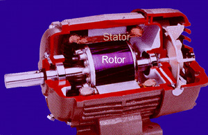
The picture shows a cutaway of a conventional three-phase, 20-hp AC motor of the type used to power equipment like fans, pumps and machinery in industrial and commercial buildings. Motors as large as this one aren't nearly so common as the fractional horsepower models found in homes and automobiles, but they're important from an energy standpoint because they often operate around the clock, and as a result, they can be responsible for as much as 75% of the electrical power consumed in a facility.
Electric current entering the motor flows through the stator, a series of copper-wire coils surrounding steel structures arranged around the inside of the motor case. The resulting electromagnetic field is picked up by conductors running lengthwise in the rotor, or armature. Here, it induces another magnetic field in scores of thin steel sheets called laminations that are stacked along the length of the rotor like ham slices in a sandwich. The magnetic field in the rotor interacts with the stator field, causing the rotor and shaft to spin.
The motor is therefore simply a device that transforms electrical energy into rotational mechanical energy. The conversion can be quite efficient but it isn't perfect, because in making the conversion, the motor consumes - or "loses" - some of the input electrical energy due to resistance offered by the stator windings and rotor conductors. Such losses are called I 2R losses after a law of physics that says power consumed in an electrical circuit is equal the product of the square of the current, I, and the resistance, R. These losses show up as heat, which can degrade the motor windings' insulation, eventually causing the motor to fail. Whether the motor fails or not, the huge amount of energy wasted by I 2R losses over the life of the motor costs its owner far more than the motor itself.
We've known for a long time that I 2R losses can be reduced by increasing the amount of copper in the stator windings, where about 65% of the motor's total losses typically occur. In years past, motors were constructed with just enough copper in the windings to produce the required output horsepower. Efficiency (low losses) was a secondary consideration. Today, thanks to an energy awareness that began during the first oil crisis of the mid-1970s and a U.S. law known as the Energy Policy Act of 1992 (EPAct), many types of industrial motors sold in the USA. since 1997 must be constructed so as to operate with improved efficiencies. Such so-called "EPAct High-Efficiency Motors" typically contain about 20% more copper in their windings than older standard-efficiency motors. Further information about high-efficiency motors is available elsewhere on The Copper Page.
Unfortunately, lowering the electrical resistance of conductors in the rotor isn't simply a matter of using thicker wires. For one thing, the rotors in most AC motors smaller than about 50 hp don't contain any wires. Instead, the conductors that carry the rotor current are in the form of bars of aluminum that are die-cast under high pressure through slots in the rotor's steel laminations. The end rings at either end of the rotor, as well as one or two cooling fans, are part of the casting.
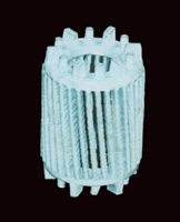
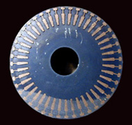
The "squirrel cage" configuration of the rotor's conductor circuit is plainly visible when the steel laminations are etched away, as in the following photograph.
The aluminum conductors' electrical resistance could be reduced by simply increasing their thickness, just as using thicker wires in the stator lowers resistance there. Unfortunately, changing the size of the aluminum conductors makes it necessary to change the size and shape of the slots in the laminations through which the aluminum is die cast, and that change would alter the rotor's magnetic properties, making the rotor (and the entire motor) larger.
The electrical resistivity of the aluminum can't be reduced since the metal is already quite pure. The ideal solution is to substitute copper for aluminum. Why? Because copper offers about 37% lower electrical resistivity than does the same volume of aluminum.
Unfortunately, as readers of previous articles in this series know, copper is not nearly so easy to die-cast as is aluminum. For one thing, copper's melting point is much higher than aluminum's, and higher casting temperatures cause the steel casting molds, or dies, to crack due to thermal shock and fatigue. Since dies are very expensive to manufacture, their high cost must be amortized over thousands of castings, and inadequate die life would make the casting process uneconomical. Even if a die didn't fail completely, a roughened or "heat-checked" surface would render the die unusable.
Another challenge facing the motor consortium's engineering team was the fact that copper must also be kept very pure until it is solidified. It dare not contain much dissolved oxygen or moisture since that could lead to porosity in the finished die casting. Maintaining a large reservoir of molten metal, as is done successfully in aluminum die casting, presents a problem with copper that would be difficult and expensive to overcome. High purity is also necessary to retain copper's low electrical resistance (or high conductivity). Even tiny concentrations of certain elements are harmful in this respect, and molten copper can dissolve sufficient iron from steel die-casting dies to raise its resistance to unacceptable values.
Development Program Addresses Technical Issues
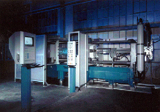
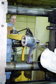
First, and in order to ensure economic viability, it was decided to perform all developmental work on a conventional die-casting machine, modified as necessary to account for the unique processing parameters associated with copper. A photograph of the machine, a 660-metric ton Buhler SC with provisions for independent computer-controlled closure and shot, is shown below.
The principal obstacle to successful copper die-casting is finding a die material that can withstand rapid and repeated excursions to copper's melting point, 1083 C (1981 F). Early on, researchers in the CDA-led consortium found, as expected, that ordinary die steels can sustain only a limited number of "shots" before checking and cracking. The engineers therefore looked at a variety of somewhat more exotic materials, including molybdenum and tungsten alloys and a space-age composite known as chemical vapor deposited tungsten.
While these materials offered significant promise, optimum results - in terms of performance, ease of manufacture and cost - were found in a nickel-base superalloy known as Inconel Alloy 617. The alloy was originally designed for use at high temperatures, and it has a well-documented reputation for resisting oxidation and thermal stress. And, since the alloy is nickel- rather than iron-based, chances for iron pick-up during casting are considerably reduced.
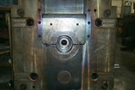
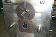
Another significant step forward was made when the research team realized that it wasn't high temperature per se that caused dies to fail, but rather the size of the temperature range between successive shots. This hunch led the team to raise die temperatures to between 600C and 650 C (1112 F and 1202 F), which proved to be sufficient to extend die life to an economically acceptable limit. This research is ongoing. For instance, it has been found that, rather than constructing an entire die from the expensive nickel-base superalloy, it is sufficient to utilize a conventional steel die block in which inserts of the alloy (and other materials, as appropriate) are placed at locations where thermal stresses are especially severe. This practice considerably reduces the cost of the die. The photo shows one of the dies used to produce a rotor casting.
Researchers also learned that instead of melting and maintaining a large quantity of copper as is done in conventional die-casting, it was advantageous to melt just enough metal for each shot, using a small high-energy induction furnace, then immediately injecting the molten copper into the die cavity. This practice minimizes the pick-up of detrimental moisture and oxygen and yields sound castings in which copper's high electrical conductivity is satisfactorily retained.
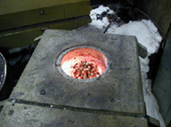
The photograph shows copper pellets being placed in the furnace crucible. Before casting, a stack of laminations is assembled on an arbor and compressed to prevent intrusion of copper between the individual steel sheets. The assembly is placed in the die, which is then closed under high pressure to prepare for the injection shot.
Once sufficient time has elapsed for the casting to solidify in the water-cooled die, the finished rotor casting can be removed and the cycle repeated. Depending on the size of the casting, each shot takes between 2 and 4 minutes.
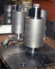
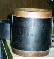
Close-up views of two completed castings are shown below.
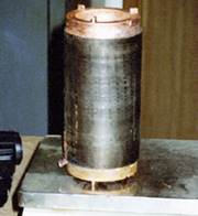
The high quality of the cast metal is evident in the cross-section of a completed rotor, below. The copper has completely filled the slots in the laminations. No porosity is evident in the photo, although a small and acceptable amount of porosity and other defects were found in the conductor bars and in some end-rings, which are bulkier and therefore solidify less rapidly. Little, if any, alloying between the copper and lamination steel could be detected. In fact, multiple tests conducted on extracted copper conductor bars indicate that the copper had retained
an average of nearly 99% of its theoretical conductivity. In some cases, conductivity was as high as 99.7% IACS, the international annealed copper standard.
What's Ahead for R&D?
The major technical hurdles have been overcome, and scores of rotors have been cast and tested. By the end of 2001, several hundred full-size commercial rotors will have been cast to demonstrate the overall viability of the copper die-casting process. Research continues, however, in order to better understand and eventually optimize process parameters for rotors within the range of sizes and types expected in commercial equipment.
And What Have We Gained?
The long-term objective of the consortium's R&D effort was to provide a new tool - the die-cast copper rotor - that would enable motor manufacturers to design motors with higher electrical efficiencies than the best models available today. That objective has clearly been achieved, but there's more good news.
All of the rotors cast to date utilized laminations with slot sizes and configurations identical to those used in aluminum die-cast rotors. While these off-the-shelf laminations provided a handy and inexpensive platform for proof-of-concept tests, they hardly represent a best-case scenario. The design of electric motors is a complex art in which improvements in one component must be complemented by changes in others in order to arrive at an optimum configuration. Motor manufacturers in the USA and elsewhere in the world are, therefore, now designing laminations that will accommodate the copper die-casting process, and at the same time, take full advantage of copper's high conductivity.
However, the most spectacular news, at least for now, is that motors fitted with die-cast copper motor rotors performed exceedingly well - better than predicted, in fact - when tested according to IEEE Specification 112, Test Method B, as required by the Department of Energy. 112 is the method used to establish EPAct efficiency requirements.
How Well?
When numerous motors with conventional aluminum rotors were compared with those with and one with a die-cast copper rotors, but not otherwise optimized - the copper motors exhibited:
- A 15 - 23% reduction in total losses compared with their aluminum counterparts. As expected, most of the improvement came as a result of lower rotor I 2R losses, but additional reductions were seen in stray-load losses, which mainly have to do with magnetic effects, and friction and windage losses, which arise in bearings and air flow from the motors' cooling fans.
- An increase of up to 1.7 percentage points in overall electrical efficiency. This is a very significant gain in itself, but even higher gains can be expected when designs are optimized to take full advantage of the new manufacturing process.
In addition,
- Operating temperatures for the copper motors fell by a minimum of 5 degrees F and as much as 32 degrees F. An accepted rule of thumb says that every 10-degree rise in motor operating temperature reduces insulation life by one-half. Therefore, motors with die-cast copper rotors should expect at least a 50% increase in operating life - and probably more, once designs are optimized. That feature alone will save the motors' owners a lot of money.
- Torque values were also reduced, another plus in terms of motor operating characteristics.
What Does It All Mean?
Using the new die-cast copper motor rotors, motor designers will soon be able to offer motors of the same size as conventional aluminum-based units, but with significantly higher efficiency than even the best motors available today. Conversely, motors with equivalent efficiency can be made smaller, lighter, and possibly less expensive than old-style aluminum versions.
It has been estimated that there are currently about 12.4 million motors of greater than 1 horsepower in service in the USA These motors account for about 23% of all the electric power consumed in the country. The Consortium for Energy Efficiency (CEE), an energy conservation organization, reports that about 2.9 million of these motors fail each year, of which 600,000 are replaced. According to CEE estimates, introducing more energy-efficient motors would annually save U.S. industry between 62 and 104 billion kWh of energy, valued between $3 billion and $5 billion, and avoid the release of between 15-and-26 million metric tons of carbon to the atmosphere. Certainly, not all inefficient motors will be replaced quickly, and many may not be replaced for years despite the savings this would provide. But the sheer numbers involved - and the potential gains to be realized - are staggering.
The investment made by the worldwide copper industry and its funding partner, the DOE, have clearly paid off: the CDA-led R&D effort has been a success by any standard. Its results have not gone unnoticed among motor manufacturers, many of whom in the USA, Europe, Latin America and Asia are already pressing ahead with plans to incorporate copper motor rotors in their products. But the best is yet to come, when the rate of the world's wasted energy consumption begins to fall, and with it, the emission of greenhouse gases. All that, thanks to a lot of ingenuity… and a little bit of copper.
Also in this Issue:
- Die-Cast Copper Motor Rotors Heading for Success