![]() Springerville Generating Station Solar Array
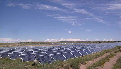
Springerville Generating Station Solar Array
Arizona produces two-thirds of the copper we use, and more than half of that finds its way into electrical products. Arizona’s other big natural resource is, of course, sunshine: 300 days of it in an average year. It’s good for tourism, and, along with copper, it’s also good for making lots of renewable electrical energy. When it comes to clean energy sources, you could say that Arizona’s copper and sunshine are “natural” partners.
Renewable energy is certainly booming. Wind energy can claim more installed capacity, but photovoltaic (PV) solar is growing fast, up from just 168 MWp (peak) installed U.S. generation in 2001 to 1,111 MWp by the end of 2008. And U.S. solar cell production capacity tripled between 2001 and 2008, a 17% cumulative annual growth rate.1
PV solar is still costly, but that could change. State-of-the-art production techniques reportedly reduce panel costs by as much as ten-fold, and some of the latest “thin-film” cell materials (the U.S. is the leading producer and a major exporter) now easily exceed 10% efficiency, with 20% in sight.2 That would help spur new demand, although government mandates reinforced by tax subsidies and utility incentives will continue to be strong market drivers.
Clean, Reliable, Distributed
PV’s strongest appeal is its cleanliness. It’s also reliable: with no moving parts to wear out, PV panels need very little maintenance; equipment warranties now extend to 20 years or longer. PV can also provide distributed generation, putting power right where it’s needed. Lastly, PV is readily scalable, meaning that it can be installed in sizes ranging from fractional watts for hand-held devices to several kilowatts for suburban rooftops, to a few megawatts for factories and commercial buildings, to large-scale solar farms tied directly to the grid. The example reported in this case study is a little different in that it supplies power to a conventional coal-fired power plant.
The Springerville Generating Station (SGS) in eastern Arizona provides power to Tucson Electric Power (TEP) and two other utilities. TEP, which serves more than 400,000 customers in southeastern Arizona, owns two 380-MW units at SGS and operates all four units at the plant. TEP also owns and operates a large grid-tied solar array at the site that helps drive the generating station’s raw water pumps (Top photo). The array reduces the station’s annual coal consumption by about seven and a half million pounds and water consumption by four million gallons. Because it’s there, about 15 million fewer pounds of CO2 enter the atmosphere every year.
The Springerville solar field is rated at 4.6 MW DC, and TEP has announced plans to expand the system to 6.4 MW DC in 2010. It has been fully operational since 2004, and until the 14-MW PV field at California’s Nellis Air Force Base was commissioned in 2007, Springerville was one of the larger PV installations in the country. Yet, few folks outside the industry even know it exists and fewer still know that much of the 44-acre facility was built by high school students, but that’s another story.
Back to TopUnique Mandate
Arizona is one of the several dozen states that require a portion of the power generated by utilities to be renewable. The Renewable Energy Standard established by the Arizona Corporation Commission (ACC) in 2007 calls for utilities to increase their use of renewable energy each year until it represents 15 percent of the power they deliver in 2025. The Springerville array has provided TEP with a head start toward achieving those goals, said Denise Richerson-Smith, TEP’s Director of Renewable and Conservation Programs.
“The Springerville field was designed in blocks," Ms. Richerson-Smith explains. "That’s the nice feature of a PV plant; you can design for a megawatt expansion, a half megawatt, or even a couple of kilowatts at a time. When this was designed, in 2001, we had about 3 MW. We steadily increased it and had all 4.6 MW in service in 2004.”
Why locate in remote Springerville? “We get better efficiency up here where the elevation’s higher, and it’s much cooler than in, say, the Tucson or Phoenix areas. The panels actually produce less power when they get hot. We also get more sunlight here than we would in Tucson or Phoenix. As a result, in this particular facility, because we own the land and we have good efficiency, we can produce power for around 10 cents/kWh.”
Back to Top104 Miles of Copper
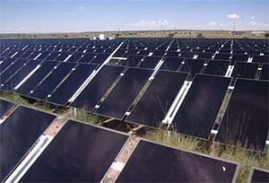 Figure 1. Copper-indium-gallium diselenide (CIGS) panels installed at SGSSS. The thin-film panels’ efficiency can reach 13%, highest among all panel types installed at Springerville.
Mark Romito knows. He’s TEP’s Commercial Renewable Program Coordinator. As he explains, “The SCSSS is divided into two sections, the first of which is 2,440 ft long by 600 ft wide and contains around 12,000 crystalline silicon solar panels. The other section, to the west, contains more than 60,000 thin-film panels. They include cadmium telluride, which is about seven to eight percent efficient, amorphous silicon at about the same efficiency, and some newer copper-indium-gallium-diselenide (CIGS) panels at around 12-13% efficiency, the most efficient we have.” (Figure 1)
“The electrical collection system is the same for all types of panels, which are arranged in rows. Panels are wired with AWG #10 metal-clad copper cables. In boxes at the end of the rows, the #10 cables are spliced to AWG #2 copper. The #2 cables, in turn, run to, and are collected in, marshaling panels (Figure 2). A DC disconnect separates the marshaling panes from inverters located just downstream. Inverters convert the 500-V DC power to 3-phase, 208-V AC. AWG 4/0 feeds power from the inverters to 208 delta-480 Y/277 isolation transformers, (Figure 3). An AC power meter is located adjacent to the transformers. From there, more AWG 4/0 feeds the 480-V power to nine large power transformers that step voltage up to 34.5 kV suitable for the grid. All cable between the inverters and the grid is AWG 4/0 copper.
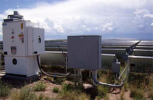 Figure 2. DC power is collected from rows of panels in row boxes (lower right). Marshaling boxes (large square panel, center) collect DC power from all row boxes in an array and feed it, by way of a DC disconnect, to inverters such as the one seen at left. Cable from panel rows to row boxes is AWG #10; AWG #2 is used between row boxes and marshaling panels. All cables are copper.
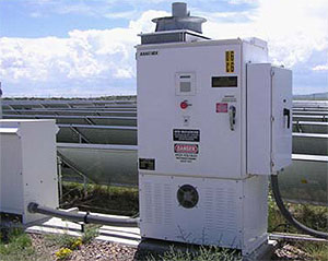 Figure 3. Inverters convert 500-V power from marshaling panels to 3-phase, 208-V AC, which, after an AC power meter, feeds all-copper, 208 delta-480Y/277 isolation transformers (left). From there, more AWG 4/0 feeds 480-V power to 480/34.5-kV step-up transformers and on to the grid.
“We have about 481,000 ft of AWG #10 metal-clad cables interconnecting the panels and feeding power to the row boxes. We have around 43,000 ft of AWG #2 between the inverters and the marshaling panels, and there are around 6,400 ft of AWG 4/0 running between the marshaling panels and the step-up transformers. All of that is copper.”
Unusual Lightning Protection Grid
The high desert of eastern Arizona sees numerous thunderstorms during the July-through-September monsoon season. There was a concern that lightning might damage the panels, but no such damage has ever occurred thanks to a unique grounding system designed by Thomas Hansen, TEP’s now-retired vice president for environmental services, conservation and renewable energy. (It was Mr. Hansen who designed and installed the Springerville solar field, and who hired the local high school students to build it.)
Marc Romito describes the system: “We have a fence around the field,” he explains, “and we have AWG 4/0 bare copper grounding cable that runs under the fence for the entire perimeter. We also have buried bare 4/0 cable that runs up the center of each PV array, as well as up the center of the field where the step-up transformers are located. The entire copper grounding grid is exothermically welded together. In all, we use about 21,000 ft of copper grounding cable.
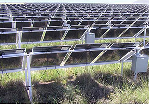 Figure 4. Power cables are run under and behind panels in an array. The massive copper grounding grid is buried beneath the arrays. Panels are simply set on the ground and are not connected to the grounding grid. Lightning energy striking the panels is conducted through the ground to the grid, in which it is dissipated and conducted away from the arrays.
It’s an innovative concept. The field has no air terminals (lightning rods) to fend off lightning; in fact, it seems unusually prone to strikes. Yet, the buried copper grid has effectively and completely protected the 44-acre facility and its 72,000 panels, plus the collection system, inverters, transformers and switchgear — all fully exposed — for several years. This is significant, and Tom Hansen’s design, with its 104 miles of copper cable, may point the way toward reliable solar energy for the future.
Back to TopThe Principals
 Denise Richerson-Smith is Director, Renewable and Conservation Program for Tucson Electric Power. She can be reached at 520-918-8339 and at [email protected].
  Marc R. Romito is Commercial Renewable Program Coordinator in TEP’s Renewable and Conservation Programs. Mr. Romito can be reached at 520-917-8710 and at [email protected].
Footnotes
 PRLog Free Press Release
- Solar cell materials fall into two broad classes: “conventional” silicon, whether mono- or polycrystalline, and thin-film materials, among which “amorphous” silicon, gallium arsenide, copper-indium-gallium-diselenide (CIGS) are commercial examples. All of these varieties are installed at Springerville.