Experimental Procedure
The two experimental heats, designated Alloy A (9.4% Al) and Alloy B (8.1% Al), comply with the compositional limits of UNS C95800 in all respects except that Alloy B falls below the minimum aluminum content of 8.5%, as shown in Table 1. In addition, commercially produced C95800, in the as-cast condition, was included as an experimental control. The composition of this alloy, identified as Alloy C, falls within the UNS C95800 specification, as shown in Table 1. Both Alloy A and Alloy B were cast, solution annealed for 5 hours at 1,000°C, and subjected to one of five different heat treatment sequences, as shown in Table 2. Some of the specimens were tempered for 6 hours at 675°C, as also indicated in Table 2.
| Alloy | Cu | Al | Ni | Fe | Mn |
|---|---|---|---|---|---|
| UNS C95800 1 | 79.0 min. | 8.5-9.5 | 4.0-5.0 2 | 3.5-4.5 2 | 0.8-1.5 |
| Alloy A | 81.8 3 | 9.4 | 4.0 | 3.5 | 1.3 |
| Alloy B | 82.6 3 | 8.1 | 4.4 | 3.7 | 1.2 |
| Alloy C | 81.8 3 | 8.8 | 4.3 | 4.0 | 1.1 |
| 1. MIL-B-24480 2. Iron content shall not exceed nickel content. 3. By difference. |
|||||
| Heat Treatment 1 | Heat Treatment Code |
|---|---|
| Alloy A (9.4% Al) | |
| Oil Quenched | OQ |
| Oil Quenched & Tempered 2 | OQ+T |
| Air Cooled | AC |
| Air Cooled & Tempered 2 | AC+T |
| Furnace Cooled | FC |
| Alloy B(8.1% Al) | |
| Oil Quenched | OQ |
| Oil Quenched & Tempered 2 | OQ+T |
| Air Cooled | AC |
| Air Cooled & Tempered 2 | AC+T |
| Furnace Cooled | FC |
| Alloy C (8.8% Al) | |
| As-Cast | As-Cast (Control) |
| 1. All Alloy A & B solution annealed for five (5) hours at 1000C, then subjected to additional heat treatment. 2. Tempered for six (6) hours at 675C. | |
One test specimen representing each of the two alloys in five conditions of heat treatment from the previous quiescent (14) seawater test was machined for reuse. In that prior quiescent corrosion test, a 6 mm hole near the top of each specimen provided a means of support. To facilitate mounting on the jet impingement test rig, a second 6 mm hole was drilled in each specimen. In addition, all traces of corrosion incurred in the quiescent seawater test were removed from the flat surfaces by machining. Hence the final dimensions varied from specimen to specimen, because machining was continued until only unattacked metal remained. The ten re-machined specimens, whose dimensions were 25.4 mm by 76.2 mm, ranged from 3.75 mm to 5.67 mm in thickness. However, the maximum variance is surface area was 9 %. No attempt was made to remove areas of corrosion present on the earlier support-hole walls. The newly purchased control, Alloy C, was machined to be similar to the other specimens in size and surface finish, which was a 120 grit equivalent. Pending testing, the specimens were individually packaged and stored. Prior to retesting, the specimens were bristle brush scrubbed with a detergent-pumice mixture, acetone degreased, air dried, measured, and weighed on an electronic balance having an accuracy of 0.0001g.
All the specimens were simultaneously tested in the jet impingement test rig shown in Figure 1. The pressure drop across an orifice is used to control jet impingement velocity. The specimens were tightly secured to the PVC fixture with by nylon fasteners. The UNS N06625 orifice plate had a 1 mm diameter hole. The impingement jet and mounting posts can be seen in one of the specimen test stations positions in Figure 1. A jet of seawater at the selected velocity strikes the center of the facing surface of the fully immersed specimens. The distance from the orifice to the specimen is nominally 10 mm. The desired test velocity was obtained by adjusting the system pressure to 2.0+/-0.1 psi (~13.8-/-0.7 k Pa) for the 15 fps test and 7.1+/-0.1 psi (~49.0+/- 0.7 kPa) for the 30 fps test. The first jet impingement test was conducted for 30 days at 15 fps (~4.6 mps). The specimens were then removed, rinsed with tap water, photographed, cleaned, reweighed and then evaluated. In accord with ASTM G-1, cleaning included a brief immersion in 10% H2SO4 at room temperature, followed by bristle brush cleaning with detergent, followed by an acetone rinse and drying in warm air. Prior to testing at 30 fps, the specimens were cleaned again, but without acid, and reweighed. They were then mounted in the reverse position, and tested for 30 days at 30 fps (~9.1 mps).
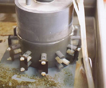 Figure 1. Jet Impingement Test Rig.
After the second 30 day seawater impingement test, the specimens were removed, rinsed with tap water, photographed, cleaned as above and weighed to determine mass loss. Multiple cleanings were required to remove the corrosion products after the 30 fps (~9.1 mps) test. In addition to mass loss, the specimens were evaluated visually and by depth of attack within the impingement zone. The latter was determined with a focusing microscope fitted with a digital depth gage.
The seawater composition and properties, as measured at the source, are shown in Table 3. The seawater temperature, as measured at the jet impingement test rig, ranged from 25.1°C to 30.8°C during the 30 day-15 fps (~4.6 mps) test, with a mean of 28.2°C and a standard deviation of 1.2°C. During the 30 day-30 fps (~9.1 mps) test, the seawater temperature ranged from 26.2°C to 31.5°C, with a mean of 29.2°C and a standard deviation of 0.9°C. Thus the mean seawater temperature difference between the two impingement tests was only 1.0°C. In the earlier quiescent test, the mean seawater temperature 29.0°C, with a standard deviation of 1.6°C which is similar to that of the jet-impingement tests.
| Temperature | 25.1-30.8°C |
|---|---|
| Salinity | 29.56 – 34.70 g/l |
| Chlorinity | 17.22 - 20.19 g/l |
| pH | 7.8 – 8.1 |
| Dissolved O 2 | 5.00 – 8.19 mg/l |
| Sulfate | 2380 – 2600 mg/l |
| Iron (Total) | 0.068 - 0.118 mg/l |
| Sulfide | <0.005 mg/l |
| Copper | <0.001 - 0.002 mg/l |
| Ammonia | <0.05 mg/l |
| Conductivity | 50.9 – 52.6 mmhos/cm |
Paper Number 05223 reproduced with permission from Corrosion/2005 Annual Conference and Exhibition, Houston, Texas