Since the prime plate is in place to protect the base metal (non-noble metal), wear is of prime concern in the design of a contact. If the prime plate is worn through, the exposed under-plate or substrate (which are non-noble systems) are susceptible to the corrosion process.
The term wear indicates the forced removal of contact material during the sliding action that occurs. This removal may be a result of the transfer phenomena (transfer of material from one contact surface to the other) or loss due to loose particles (debris) caused by the mating action. There are three wear mechanisms:
Abrasive
Wear resulting from rough, sharp hard materials or a combination thereof in contact with a softer material. An example of these surfaces are the lead-in chamfer of a printed circuit board, screw machine products, blunt end mating pins, etc.
Brittle Fracture
This is the cracking of a plated surface perpendicular to the direction of sliding. This type of wear can occur on low strength materials or a poorly controlled plating process.
Adhesive
This is the most common type of wear. It results from micro cold welding. It is force dependent. The higher the normal force systems, the more susceptible the surfaces are to this type of wear.
The figure below is an example of wear on copper (soft) and beryllium copper (hard) with and without nickel under-plate. The wear index is defined as the % exposure of the under-plate or substrate in the wear track. The term "passes" indicates the number of mates and unmates. The gold thickness was 30 micro-inches of hard gold. This data indicates the wear capabilities as a function of base metal hardness, load and the influence of the nickel under-plate.
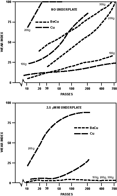 Figure 5. Wear versus Cycle
The wear rate sharply increases from mild to severe usually when a specific load is achieved as illustrated in the figure below. It is generally severe in the early stages of sliding and decreases as the sliding progresses due to work hardening of material. The flat (pin, post, tabs, etc.) is the element that is generally worn.
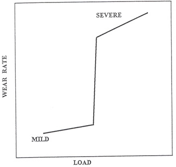 Figure 6. Wear Rate versus Load
| Characteristic | Mild | Severe |
|---|---|---|
| Metal Transfer | Little | Much |
| Wear Debris | Little or None | Heavy |
| Wear of Contacts | ~Symmetrical | Nonsymmetrical |
| Topographic Changes |
Burnishing | Rough |
| Metallurgical | Little Hardening and Subsurface Deformation |
Much Hardening and Subsurface Deformation |
| Friction | Low | High |
| Wear — Adhesive |
As previously indicated, hard plates decrease wear. The following tables are the relative hardness of various platings (Knoop hardness).
| Soft | Hard | ||
|---|---|---|---|
| Tin Leads | 7-12 | Hard Gold | 160-220 |
| Tin | 8-35 | Palladium | 220-300 |
| Pure Gold | 40-90 | Nickel | 150-550 |
| Silver | 40-185 | Rhodium | 800-1000 |
The hardness of a contact system is a composite composed of the base material, under-plate and prime plate. Example:
- Hard Gold on Soft Copper Substrate 50-75
- Hard Gold over Nickel on Copper Substrate 125-175
- Hard Gold over Nickel on Beryllium Copper 200-300
A mismatch of hardness such as item c mating to a pin such as item a and possibly item b will also result in increased rapid wear.
A useful equation to understand wear is the expression V = (K F L)/H Where V = Volume of material removed F = Normal Force L = Transitional Distance H = Material Hardness K = Factors, ie lubricity, surface roughness, contact geometry.
Use of a contact lubricant can enhance the durability of a finish system particularly when hard plates are used. This enhancement may be in the order of 10 times.
The basic wear ranking of contact finishes is contingent on the variables listed above with the following values:
| Adhesive | |
|---|---|
| Pure Gold,Tin,Thin Gold (<30 microinch) Silver | Low 10's cycles |
| Hard Gold (30 microinch), Lubricated Silver | 100 cycles |
| Hard Gold (50 microinch) | 500 cycles |
| Lubricated Gold, Pd Ni | >1000 cycles |
Although tin (alloys) plating is soft and forms a hard brittle oxide, it can be an effective plating as shown in the figure below. If a proper thickness and normal force are implemented, the hard brittle oxide will be fractured exposing the soft ductile plate under the oxide and thus will maintain stable contact. If a hard oxide is over a hard substrate, the fracture of the oxide can only be achieved with a significantly higher force which may not be practicle as a result of other design considerations.
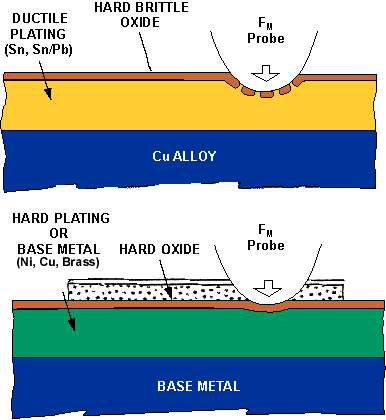 Figure 7 . Schematic Representation of Wear