- The Importance of Good Grounding
- From Newsprint to New Economy
- Copper Tree
- Lightning Protection
- Sized Conductors
- Good Installation Practice
- Inexpensive Insurance
By some estimates about two to three percent of all electricity generated in the USA today is used by or for the Internet. 1,2 Some of that power goes into making chips, but most of it is spent simply moving data. We dont see the power in use because much of the action takes place behind locked doors in unremarkable, often windowless buildings called Internet data centers (IDCs), also known as telecom exchanges or collocation centers and, less formally, as Internet hotels, server farms and carrier condos. Theyre home to all sorts of Internet-related companies, through whose servers, routers and modems flow the bits and bytes of modern e-commerce.
 The Downtown Phoenix Telecom Exchange (DPTE) houses a 380,000-sq ft (35,300 sq m) Internet hotel in the former offices and printing plant of the Arizona Republic. Restructuring the 50-year-old building for its new role meant replacing the entire electrical system with a modern, 100% copper system designed to ensure maximum power quality and reliability.
That sensitive electronic equipment, along with the air conditioners needed to keep it cool, is responsible for the IDCs large power demands. The raised-floor, equipmentfilled rooms of an IDC can use three to five times more electric power per unit area than conventional office space. 3 It has been estimated that a fully occupied 500,000-sq ft (46,500-sq m) Internet hotel can consume as much power as an equivalently sized factory or even a small airport. 4
But the sheer size of an IDCs power demand is only one of its striking features; the other is its demand for high power quality.
- First, the power must be ultrareliable. IDC tenants now ask for six nines (99.9999%) reliability and theres talk of nine-nines (99.9999999%) being needed in the future. To achieve those levels, IDCs are equipped with redundant utility feeds, uninterruptible power supplies (UPS), and diesel-driven or battery back-up.
- Second, the power has to be squeaky clean, free from noise, voltage fluctuations, harmonic distortions and stray currents.
Clean power. Thats the copper connection.
The Importance of Good Grounding
IDC tenants normally ensure that all of their sensitive electronic equipment operates at a uniform and constant ground potential by installing equipotential grounding (EG) systems, also known as performance grounding or signal reference grounding systems near the equipment in question. An EG system is not electrically separate from the buildings conventional equipment grounding and lightning protection systems; it is simply another part of the overall system, physically located at the user end of the service. In fact, all three elements of the grounding system safety, lightning protection, EG are electrically bonded, as required by the National Electrical Code®. EG systems do differ somewhat from conventional grounding systems in that they are designed to present minimum impedance at frequencies ranging up to tens of megahertz. The IDC owners responsibility is to furnish a common, high-quality (low-resistance, low-impedance) grounding system for the entire building.
But, many IDCs are established in older buildings in central business districts near potential customers and highcapacity communications trunks. Such buildings, attractive as they might be to an IDC developer, unfortunately dont ordinarily have the type and quality of electrical systems that sensitive electronic equipment requires. An electrical retrofit is usually necessary.
Back to TopFrom Newsprint to New Economy: The Downtown Phoenix Telecom Exchange
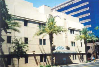
Such is the case with the Downtown Phoenix Telecom Exchange (DPTE) (Top Image). This five-story, 380,000-sq ft building was built in 1947 as the printing plant for the Arizona Republic, the states leading daily newspaper. In 1999, the building was bought by Sterling Networks, Inc., a subsidiary of Sterling Capital, a Northbrook, Illinois-based venture capital organization that currently owns or controls more than 5 million square feet of commercial real estate across the country. Sterling transformed the building into an Internet hotel.
Doug Newcomb is vice president, Sterling Network Services, at the Downtown Phoenix Telecom Exchange. When he took on the job, he brought with him 30 years of experience in the communications industry, much of it gained at AT&T, Bell Laboratories and Lucent Technologies.
The reason were successful at the DPTE is that Sterling was 10 months ahead of the market, says Newcomb. Were in an ideal location in terms of power and network availability, as well as security. But, we found that Arizonans would rather keep their solid old buildings than tear them down and build new ones, and a lot of the older office space isnt equipped for the quality of power that our tenants need.
Sterling fixed that by entirely gutting the old printing plant, removing every wire and cable downstream of the utility disconnects. In its place, Sterling installed an electrical system specifically tailored to the needs of an IDC. The Smith Group, a Phoenix-based architect-engineering firm, designed the new system.
Smith took advantage of the buildings four existing 4000-A/480-V services (supplied by Arizona Public Service) but added three motor-generator sets (rated at 135-, 750- and 1500-kW) as backups. The two larger units back up utility power; the small one is reserved for life-safety systems. Tenants can utilize this backup system or install their own, as several tenants have elected to do. Generator sets are located in the subbasement.
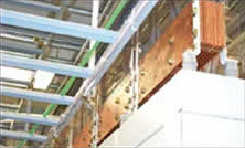 Figure 1. Electrical systems in Internet data centers are designed to accommodate higher power densities than those in conventional office space. The robust power buses shown here seem more appropriate for heavy machinery than for racks of electronic equipment. Power usage in IDCs has not been as high as originally anticipated, but power quality requirements remain more stringent than those of almost any other industry.
A few tenants initially told us they also wanted to install their own grounding systems, complete with individual grounding electrodes. The City of Phoenix was willing to go along with the idea, but I wouldnt permit it ground loop currents would have degraded our systems power quality. We furnish the buildings only central grounding system, with access points at each tenants facility. It took us awhile to make our point, and it turned out to be a learning experience for the city inspectors, but they eventually approved our plan.
Incidentally, I have the ground resistance of our system checked twice each year by a competing utility, not by Arizona Public Service, which supplies our power. That way I know the company doing the testing has no vested interest in the results.
Back to TopCopper Tree
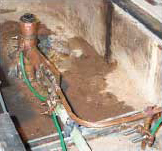 Figure 2. Connections between original grounding electrode conductors at the upper and lower terminal stations were found to be questionable. Some mechanical connectors, while acceptable in many applications, are not recommended for below-grade installations such as this. Corrosion between dissimilar metals, even if only slight, can contribute to high ground resistance values.
The grounding system resembles a tree, with a low resistance electrode as its root. The 20-ft deep, chemical type electrode is located near the center of the subbasement (Figure 2). The electrode is surrounded by bentonite, which retains moisture and helps ensure good earth contact. The electrodes resistance is checked twice yearly and has remained between 3.0 ohms and 3.5 ohms. Electrodes could not be installed outside the building because it extends to the property line on all sides.
A single length of insulated 750-kcmil tinned copper cable connects the grounding electrode to the office principal ground bus (OPGB), a 1/4-in x 4-in x 48-in (6 .3-mm x 100- mm x 1,219-mm) copper plate mounted on a nearby wall, midway between the buildings north and east service entrances (Figure 3). The OPGB can be thought of as the main trunk of the grounding tree. All grounding circuits in the building terminate at this plate.
Connections to the OPGB are arranged in the PANI pattern (see Sidebar). Two insulated 750-kcmil tinned copper conductors extend from the top center of the OPGB as the buildings two vertical grounding risers. These conductors, which are continuous (not spliced) along their entire length, are the trees main branches. They extend along the inside of the buildings east and west exterior walls and terminate at master ground bars (MGBs) at the roof level.
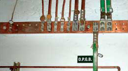 Figure 3. The OPGB is the heart of the DPTE's grounding system. The 750-kcmil tinned copper grounding electrode conductor is bonded to the 1/4-in x 4-in x 48-in (6.3-mm x 100-mm x 1,219-mm) copper bar from the bottom. Two 750-kcmil vertical risers (green insulation, center right) connect to main grounding bars on all floors. Other conductors (top left to right) connect to the emergency power supply transformer, lightning protection system, building steel (east side of building), sprinkler standpipe, water line, building steel (north side of building) and the building's north and east electrical vaults. Connections to the bar follow the PANI convention.
Other all-copper connections to the OPGB (left to right in Figure 3) include bare AWG #6 to the emergency power system transformer, AWG #4 to the lightning protection system, bare 350 kcmil to building steel, AWG 4/0 conductors to the sprinkler standpipe and water line, (Figure 5), another bare AWG 4/0 to building steel, and a pair of bare 750-kcmil conductors to the buildings north and east electrical vaults. All conductors are tagged for identity at termination points.
Connections between the MGBs and tenants EG grounding systems are made via conductors routed along overheadcable trays to equipment cages, where they terminate at overhead- or wall-mounted grounding bars. Grounding conductors for large tenant areas are also routed along suspended trays. Thus, the DPTEs raised floor is actually overhead (Figure 6).
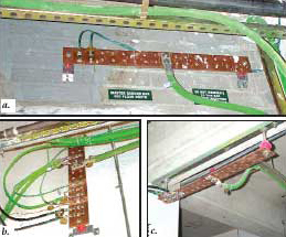 Figure 4. Two main grounding bars (MGBs) are installed on each floor, one for each vertical riser. The risers are continuous lengths of 750-kcmil tinned copper, to which the bars are securely bonded. The 1/4-in (6.3-mm) thick copper MGBs are mounted on insulated standoffs and are positioned either horizontally (a), vertically (b), or overhead (c) to facilitate access.
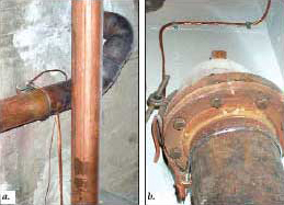 Figure 5. (a) Connection to the main water service, as required under 250 of the National Electrical Code. Mechanical bonds, such as the one used here, should only be made using approved copper alloy clamps. AWG 4/0 bare copper leads directly to the OPGB. (b) Another AWG 4/0 conductor connects the sprinkler system standpipe to the OPGB.
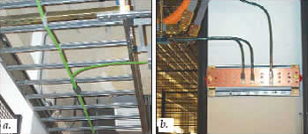 Figure 6. Tenants' equipment is located in cages or secured floor space. Equipotential grounding (EG) systems minimize electrical noise between networked equipment. Connection to the building's common grounding system is made via AWG 4/0 (or larger) copper conductors routed along overhead cable trays (a) to local grounding bars (b). Note that in this case, the EG systems' "raised floor" is actually overhead.
PANI CONNECTIONS
Below is a generalized view of the PANI convention for arranging connections to a main grounding board. PANI segregates surge Producers, surge Arresters, and Non-isolated and Isolated networks. Its objective is to miminize impedance to earth in the event of a lightningor fault-induced surge, thus giving maximum protection to safety-grounded, networked equipment. The MGB is constructed from 1/4-in (6.3-mm) copper plate, 6 in (156 mm) wide. Length may vary. A similar sequence of connections is used at all MGBs in the building. (Source: United States Department of Agriculture Rural Utilities Service Bulletin 1751F-810, Electrical Protection of Digital and Lightwave Telecommunications Equipment.)
Lightning Protection
Franklin-type air terminals protect HVAC equipment and an antenna tower located on the roof. A continuous ring of braided copper lightning cable connects the terminals, and an extension of this cable is bonded to the roof levels MGB. A riser bonded to the MGB connects to the P quadrant of the OPGB.
Down-conductors are connected to the rooftop ring at approximately 100-ft (30-m) intervals. These conductors run along the inside of the buildings exterior walls and are bonded to copper-clad ground rods driven near the periphery of the subbasement. In addition, one down-conductor is bonded to the MGB on each floor. A ring of copper lightning cable connects the lightning-protection electrodes, and an AWG 4/0 lead from this ring is bonded to the OPGB. Braided copper lightning cable is preferred over solid conductors for connections between air terminals and earth because the cables relatively large surface area facilitates the conduction of high-frequency lightning discharges.
Back to TopConductors Sized for Specified Resistance
All of the DPTEs grounding conductors are sized to maintain resistance below fixed levels, either 0.005 ohm or 0.010 ohm for the length of the conductor run, as specified in the Lucent standard upon which the system is based. For example, there is a maximum resistance (for each leg) of 0.005 ohm between the OPGB and the grounding electrode, between the OPGB and MGBs on individual floors, between MGBs and subsidiary grounding bars at tenants equipment and between MGBs and branch-circuit panel boards. Resistance is held to less than 0.010 ohm between the OPGB and building steel, the main incoming water line, backup generator sets, cable entrance ground bars, and lightning protection grounds.
Table 1 lists maximum conductor lengths for common wire gages at the two resistance levels in question. Using the table, the grounding conductor size for each leg of the various circuits can be selected based on the length of the leg and the resistance limit for type of service being protected.
The table refers to resistance only and does not consider high-frequency surge currents, for which appropriate impedance limits should be established.
| Conductor Size | DC Resistance (English/Metric) |
Objective Resistance | |
| 0.005Ω | 0.010Ω | ||
| #6 AWG | 0.4110/kf 1.348/km |
12 f 3 m |
24 f 6 m |
| #4 AWG | 0.2548/kf 0.8478/km |
19 f 5 m |
38 f 11 m |
| #3 AWG | 0.2050/kf 0.6726/km |
24 f 7 m |
48 f 14 m |
| #2 AWG | 0.1625/kf 0.5331/km |
30 f 9 m |
61 f 18 m |
| #1 AWG | 0.1289/kf 0.4229/km |
38 f 11 m |
77 f 23 m |
| 1/0 AWG | 0.1022/kf 0.3353/km |
48 f 14 m |
97 f 29 m |
| 2/0 AWG | 0.0802/kf 0.2631/km |
62 f 18 m |
124 f 37 m |
| 3/0 AWG | 0.0636/kf 0.2087/km |
78 f 23 m |
157 f 47 m |
| 4/0 AWG | 0.0505/kf 0.1657/km |
99 f 30 m |
198 f 60 m |
| 250 MCM | 0.0440/kf 0.1444/km |
113 f 34 m |
227 f 69 m |
| 300 MCM | 0.0367/kf 0.1204/km |
136 f 41 m |
272 f 83 m |
| 350 MCM | 0.0314/kf 0.1030/km |
159 f 48 m |
318 f 97 m |
| 400 MCM | 0.0275/kf 0.0902/km |
181 f 55 m |
363 f 110 m |
| 500 MCM | 0.0220/kf 227 0.0722/km |
227 f 69 m |
454 f 138 m |
| 750 MCM | 0.0147/kf 0.0482/km |
340 f 103 m |
680 f 207 m |
| Characteristics of Bare Copper at 68°F (20°C) | |||
| (Source: United States Department Of Agriculture Rural Utilities Service BULLETIN 1751F-810, Electrical Protection of Digital and Lightwave Telecommunications Equipment.) | |||
Good Installation Practice Ensures High Power Quality
Several other features of the DPTEs grounding system are worth noting:
- Grounding conductor floor penetrations are sealed with polyvinyl chloride (PVC) (Figure 7). Metallic materials such as steel conduit should not be used in such locations because of the possibility that a high-magnitude surge current (as from lightning or a large ground fault) might occur along the enclosed grounding conductor inducing large currents, resistive heating and a possible fire hazard if metallic penetration sleeves were used.
- When grounding conductors are intentionally routed inside metallic conduit (for shielding, for example), the conduits are bonded to the conductor at both ends. Figure 8 shows an example as installed by a DPTE tenant for its grounding system. Encasing grounding conductors in this manner is an IEEE recommended practice. It avoids increased voltage drop along the conduit during a surge and takes advantage of the lower voltage drop offered by the large-diameter conductor. 5
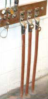 Figure 7. Penetrations through floors are lined with PVC to avoid the risk of fire. Metallic penetrations can suffer hazardous resistive heating when large surge currents pass through the grounding conductors. Connection lugs are tinned copper.
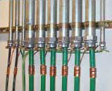 Figure 8. In most instances, large grounding conductors at the DPTE are not encased in conduit, but one tenant elected to do so in its system. The IEEE-recommended practice for this installation calls for bonding the conductor to the conduit at both entrance and exit points.
- Bend radii in runs of grounding conductors are no smaller than 1 ft (305 mm) to maintain low inductive reactance along the full length of the conductor (Figure 4).
- Grounding conductors are continuous between terminations. While there are bonds to the conductor, there are no splices along its length. Bonds are made exothermically or by means of approved copper- alloy clamps (Figure 4).
- Connections to ground bars are made with tinnedcopper lugs fitted with tamper-resistant (pentagonalheaded) bolts. All bars are clearly labeled, and all conductors are tagged with routing and termination information (Figure 9).
Sterling installed a Reliable Power Meters (RPM) Multipoint Power Quality monitoring system to keep track of power quality on a real-time basis (Figure 10). Timm Davis, of Phoenix-based Davis Technological Solutions ([email protected]), whose company oversaw the installation, explains: We have meters on the buildings incoming power service and on each tenants service, allowing us to continuously monitor all aspects of power and power quality, especially the harmonics, which can adversely affect other tenants. That way, if a tenant has a problem, we can trace down the source and recommend a solution.
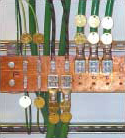 Figure 9. Tinned-copper lugs connect grounding conductors to ground bars. Bolts have tamperproof pentagonal heads. All grounding conductors are tagged for identification and termination points.
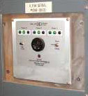 Figure 10. A system provided by Reliable Power Meters (RPM) continuously monitors and logs such power quality parameters as voltage, current and waveform.
Inexpensive Insurance
Doug Newcomb believes that the grounding system installed at the DPTE, large as it is, was relatively inexpensive. The cost of the building and its reconstruction came to around $25 million, says Newcomb. About one quarter of that went to the electrical infrastructure, including $260,000 for new transformers.
New breakers for the four service sections cost between $23,000 and $33,000. The grounding system itself cost about $300,000. That sounds like a lot of money for grounding, but it really isnt much when you compare it with the total cost of the reconstruction.
And remember, says Newcomb, this is a pretty large building; it covers an entire block and were protecting five floors. We used only top-quality, full-sized tinned copper conductors as recommended in the Lucent Technologies specifications, but even so, the copper was a small cost item compared with labor and building prep costs. Incidentally, the Lucent Technologies specs we used at the DPTE are still the standard for the telecommunications industry. Everyone uses them.
Finally, you have to compare the cost of the system with the cost of the equipment and data it protects. Our tenants come to us expecting reliability, security and flawless power quality. Our grounding system guarantees that theyll get it.
Think about that reliability the next time you send an email. Copper makes it happen.
Back to TopThe Principals
 Doug Newcomb is vice president, Sterling Network Services, at the Downtown Phoenix Telecom Exchange. He was responsible for a major portion of the reconstruction undertaken by Sterling Networks when it converted the 50-year-old Arizona Republic printing plant to a modern Internet hotel. Mr. Newcomb can be reached at [email protected].
Footnotes
 Kawamoto, Kaoru, J.C. Koomey, B. Nordman, R.E. Brown, M.A. Piette, A. Meier, "Electricity Used by Office Equipment and Network Equipment in the U.S.," LBNL 45917, U.S. Dept. of Energy, August 2000.
- Stahlkoph, Karl E. and J.H. Douglas, "Energy Infrastructure for a Digital Economy," Electric Power Research Institute, Palo Alto, California, 2001.
- The term, "raised floor" refers to installations in which the signal reference grid is located under sensitive electronic equipment in a subfloor plenum or beneath floor covering. Raised floors are commonly used, but the reference grid or ground plane can just as well be located above the equipment.
- Dresher, W., "Copper in the New Economy," Proc. Cobre/Copper '03, Santiago, Chile, December 2003.
- IEEE Std 142-1992 (The Green Book), 2.2.3 -6. Institute of Electrical and Electronic Engineers, Inc., Piscataway, N.J.