![]() Download PDF Version [2.8Mb]
Download PDF Version [2.8Mb]
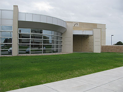
CoSentry’s Midlands Data Center in Omaha, Nebraska is built to the highest published redundancy standards to ensure maximum uptime for its data-sensitive clients. 100% copper power cable and a robust, all-copper grounding system are key elements of the center’s enviable reliability.
Most of today’s data centers are designed and constructed to meet reliability standards developed in large part by the Uptime Institute1. The standards are based on the degree of redundancy built into a center’s mission-critical systems. The objective is to provide instantaneous backup should an interruption occur in any of those systems. The Institute’s four “Tier” levels are based on the degree of redundancy present. Tier I denotes basic reliability capability; Tiers II and III command the largest share of the data-center market, while Tier IV centers are mainly populated by clients with the most stringent uptime requirements.
The Midlands Data Center (MDC) in Omaha, Nebraska is one such center. Built and operated by CoSentry, the bunker-like facility is regarded as the flagship among the company’s six interconnected and mutually sustained centers. CoSentry operates one other center in Omaha, plus two each in Kansas City and Sioux Falls.
MDC comprises 10,000 square feet of raised-floor data space, one-seventh of the company’s total capacity (2013 figures). An additional 5,000 sq ft will be added in mid-2014. The center was physically designed to Tier IV standards but is not formally certified by the Institute. Omaha being in the heart of tornado alley, MDC was constructed to withstand winds up to 240 mph. And, like other CoSentry centers, it is also fully compliant with NIST800-53, ISO 27001 and other NIST information security standards, SSAE 16, FISMA, COBIT and SoX/GLBA, plus LEEDS and Energy Star ratings.
The Power System
MDC receives its primary 12-MW, 13.8 kV power via direct paths to two Omaha Public Power District substations. Upon entering the site, the feeds first pass through an automatic throwover switch. Should one power source leg fail, the switch automatically transfers power to the other leg. Each output leg from the ATO feeds one of the center’s two 4,000-A, 13.8 kV – 480 V step-down transformers, Figure 1, each of which can satisfy the center’s entire load. A third transformer will be added as the center expands.
The two current emergency generators are rated at 2.5 MW and 2.25 MW, respectively, Figure 2. Each has sufficient power and fuel reserve to operate the center at full capacity for three days. Both generators run for 20 minutes weekly and serviced quarterly. An additional generator can be installed as the center expands.
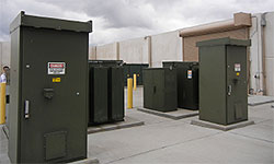 Figure 1. Utility power from two independent substations enters the data center through an automatic throwover switch, from which it is fed to two 4000-A, 13.8 kV – 480 V transformers, each of which can supply the entire center if needed. 480 V power is fed to the data center as independent and redundant A and B circuits. Each circuit comes off a separate power distribution unit (UPS) and a separate uninterruptible power supply (UPS), backed up by battery farms inside the structure.
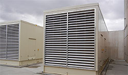 Figure 2. Two emergency back-up generators, housed in tornado-proof enclosures, are rated at 2.5 MW and 2.25 MW, respectively. Each is sufficiently sized to power the entire center for three days with installed fuel reserves. A third generator is scheduled for installation in late 2014.
Power enters the data center structure through two electrical power rooms. Each room serves one of the center’s two 5,000-sq ft data suites. The power rooms house the building’s two service entrances, each rated at 4,000-A including a 4,000-A entrance for the emergency generators. Each room also has one 750-kW UPS rated at a less than 12 second response time. The UPSs are backed up by seven minutes battery power (generators spool up in 12 seconds). Also in the power rooms are three 800-A PDUs. Surge suppression devices (SSDs) protect circuits against unanticipated changes in circuit potentials, Figure 4. Each of the PDUs has an 800-A static switch to alternate between power sources. The primary sources are the UPSs in the power rooms; the second, redundant source is a catcher UPS located in another part of the building. It is sized to run the entire building and takes over when there is an issue with the PDUs. Power transfer takes less than four MS, which is faster than any computer on the data floors can see. Switches also enable circuits to be isolated when needed, such as for maintenance.
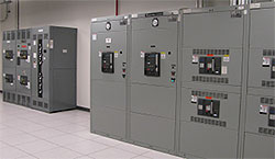 Figure 3. A portion of one of two electrical rooms at MDC showing redundant breakers, UPS units with maintenance bypass switches to isolate A and B circuits when needed.
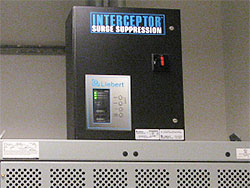 Figure 4. Two surge suppression devices, one atop the cabinet and one (labeled TVSS) on the cabinet’s upper shelf, protect equipment against voltage irregularities.
A and B circuits are delivered to separate remote power panels (RPPs) located at the ends of data aisles, A on one end of an aisle and B on the other, with 24 cabinets between. Sub-floor cables from the RPPs feed the server racks. Cables are sized at a minimum of #10 AWG, which is one size larger than that required by the National Electrical Code (NEC) for 20-A service. In fact, most circuits on the raised floor are rated at 30-A, for which CoSentry uses #8 AWG cable. “It’s all about heat re-distribution with the larger-gage wiring”, explains Scott Capps, CoSentry’s Central Region Facilities Manager.
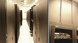 Figure 5. Power density ranges from 3,000 W/sq ft to 6,000 sq ft in plenum-cooled aisles (left), but one client requested 20,000 W/sq ft, which CoSentry accommodated by installing “chimneys” above the server racks (upper portion or photo, right). Redundant fans powered by VFDs draw heat from the chimneys based on air pressure and temperature.
“Power density is 150 W/sq ft on the data center floor,” notes Mr. Capps. We’re shooting for 3,000 W/cabinet in a 5,000 sq ft suite. That’s 250 cabinets. We can add as much power as needed through UPS units, but the real issue is how to extract the heat. We can take our racks to 6,000 W, and we don’t have any problem with that, either with power or cooling. We actually have one client who needed 20,000 W/cabinet, and we handled that by closing off the back of the racks and venting the trapped heat through a chimney. The chimneys have redundant fans that are driven by VFDs so they can ramp up and down based on the air pressure and temperature inside the cabinets, (Figure 5).
Energy-Efficient Cooling
The same level of redundancy found in power circuits is present in the center’s cooling system. Two 550-ton Carrier chillers operate on individual electrical supplies. They don’t even share panels. One chiller normally runs while the other idles. A third chiller will be added in 2014.
MDC is LEEDS and Energy Star-compliant, and Mr. Capps is quick to point out that those ratings depend in part on the cooling system, which is designed for high efficiency. “It can operate during cold months using only its water-side economizers, i.e., by turning the chillers off and simply allowing cold air to provide cooling via a pair of water towers, saving us about 100 kW (Figure 6). For added efficiency, the cooling system’s pumps are powered by NEMA Premium-Efficiency® motors driven by VFDs to adjust for load. NEMA Premium-motors gain their superior efficiency by incorporating approximately 20% more copper in their windings than standard motors, reducing I2R losses enough to pay off their purchase cost within a year or two.
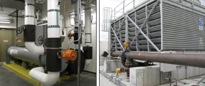 Figure 6. Left: One of MDC’s two 550-ton chillers runs while the other remains on standby. Each is completely independent from the other, not even sharing the same electrical panel. All motors in the cooling system are NEMA Premium-rated to save energy and extend motor life. Right: Additional cost savings are gained by the use of water towers that allow atmospheric cooling during winter months.
A Really Robust Grounding System
“Data centers are special,” says Scott Capps. “They’re not built as a commercial building and they’re not built as a factory. The redundancy levels here are so far above those structures. Redundancy and proper grounding are among the top items we have to stay aware of. Grounding is very important. For one thing, we generate a lot of harmonics that come along with any non-linear circuit. Those harmonics will cause many kinds of issues in, for example, our UPS and battery systems. If you don’t have proper grounding you’re going to have many problems throughout the years.
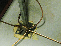 Figure 7. A 4-ft square grid of bare #4 AWG copper grounding conductors covers the entire sub-floor space in each data room. It is bonded to similar #4 conductors descending from equipment and server racks above. The grids connect downstream to grounding buses, one for each room, and from there to the main grounding bus.
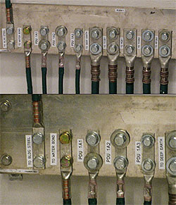 Figure 8. The main grounding bus for the #1 data room in the MDC (upper photo) bonds conductors from all system elements in that room. Note that all leads are labeled for ease of maintenance. The close-up (lower photo) shows leads from building steel, the water system and various PDUs, as well as the outgoing lead to the deep-earth electrode.
“All of our equipment is grounded. That includes server racks, RPPs, PDUs, UPSs, battery racks, transformers and switches — anything metallic inside or outside the center that can contact electricity.
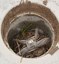 Figure 9. This 20-ft copper-clad deep-earth electrode serves as the single point at which all elements of the data center’s interior and exterior grounding systems ultimately terminate. The 500-MCM bare copper grounding conductor seen at the top connects with the MGB inside the structure. MDC annually inspects and maintains the electrode to ensure a maximum earthing resistance of four ohms. Resistance measured two ohms are the center’s most recent re-commissioning.
“Inside the data rooms, grounding conductors from racks and equipment are bonded to a 4-ft square grid of #4 AWG bare copper located in the subfloor space (Figure 7). The grids — one for each room — are connected to wall-mounted grounding buses, and from there to the main grounding bus for that room (Figure 8). Finally, the buses, along with all exterior system elements, including the ground ring surrounding the structure and the lightning-protection electrodes on the center’s roof, are connected to the deep-earth ground.
“The deep-earth ground is a 20-ft copper-clad electrode located in our transformer yard (Figure 9). All grounding connections in the data center ultimately lead to this electrode. Our ground-resistance requirement was four ohms, but we like to maintain a maximum of two ohms at this point, and that’s checked once a year to make sure it hasn’t risen.”
Leading to the electrode is a 500-MCM bare copper grounding conductor that runs underground from the main grounding bar (MGB) located inside the center. Additional 500-MCM copper runs from the MGB to each continuing grounding bar, one of which is shown in Figure 8.
Copper Connections Only
”CoSentry has a standard that requires copper connections only,” says Mr. Capps. “We do not accept any aluminum connections, first, because aluminum is not as good a conductor as copper. Besides that, we’ve had problems with aluminum connections coming loose on legacy equipment (since replaced), and we were constantly on a re-torqueing scheme. We do have an annual torqueing scheme for all connections, but with aluminum I’d almost like to do it weekly. So we simply do not allow aluminum. Everything in this building is copper-only.
“Also, in the end, copper cost less. Among the other issues we’ve seen with aluminum is that the conductor has to be larger, and the conduit has to be larger, and you’re trying to fit all of this into a very small footprint and inside a small piece of electrical gear. So if we have an electrician working in an area that’s very hard for him opposed to one that’s easier, we know that you’re going to get much better quality if it’s easier for the electrician to do. That means you don’t have to do it over, and that translates to lower maintenance costs. In my mind, those lower maintenance costs can make the life-cycle cost of copper much lower than that of aluminum.”
Copper: more reliable, and it costs less in the end.
The Principal
 Scott Capps is CoSentry’s Central Region Facilities Manager and is based at the Midlands Data Center. Mr. Capps holds a degree in construction management and is also an electrician. He can be reached at 402.970.8596 and [email protected].
Footnotes
 The Uptime Institute is an independent division of The 451 Group, a research, advisory and professional services firm serving the IT industry. Uptime Institute describes itself as an unbiased, third-party data-center research, education and consulting organization that provides, among many other services, certifications that formally attest to the reliability capability of commercial data centers. Not all data centers subscribe to the Institute’s certification program although most design and build to its Tier standards, relying on their customers’ audits to confirm those claims