Copper tube for underground water services or other underground piping applications can be installed using various installation methods. Click on the links below to learn more about each step.
- Tube End Preparation
- Sleeving / Wrapping
- Installation Methods and Considerations
Tube End Preparation
Underground copper tube can be joined to the water main, corporation stop, water meter, meter-yoke, etc. using various joining methods such as compression joints, flared joints, packed joints, and soldering or brazing — although less common — where permitted.
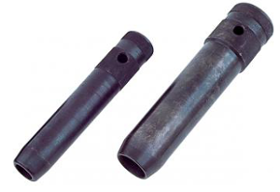
Photo Credit: Reed Manufacturing Company
Regardless of the joining method chosen, installers should follow a few simple, yet very important steps:
- Ream the cut end of the copper tube so that the inside burr is removed and the interior bore is returned to the full interior diameter. A burr left on the inner diameter of the tube end can create an imperfect sealing surface where metal-to-metal contact is made with the flared, compression or packed joint. This can be easily avoided using a variety of reaming/deburring/chamfering tools.
- Deburr or chamfer the outside diameter of the cut copper tube end so that the burr formed during the cutting operation does not nick or damage the gasket in the compression or packed joint. This can be accomplished using a file, O.D. chamfering tool or other appropriate tools (Refer to Figure 11.9 and Figure 11.10).
- Straighten and re-size/re-round the ends of the copper tube. As copper tube is uncoiled or rolled-out – or with trenchless methods of installation as the tube is pulled through the ground – the tube end can easily become out-of-round, oval, bent or dented. To make satisfactory, strong, reliable, leak-free joints, the installer should re-size and re-round the tube end using an appropriate resizing tool.
Photo Credit: Reed Manufacturing Company
Straightening and re-sizing/re-rounding the tube end is important because it must engage the sealing surfaces of the fitting securely around the entire diameter of the fitting, otherwise a leak can occur. In flared joint of Figure 1, the inner surface of the tube end forms the seal against the shoulder of the flare fitting. A straight, round, reamed and chamfered tube end is essential in forming a leak-free joint. In the packed joint of Figure 2, the gasket forms a seal around the outside surface of the tube. Here again, a straight, round, reamed and chamfered tube is essential in establishing contact with the gasket around the circumference of the tube and the inside diameter of the fitting providing for a leak-free connection.
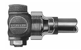
Figure 1
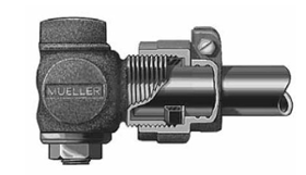
Figure 2
Photos Copyright: Mueller Co., LLC. Used with permission.
Sleeving / Wrapping
In most cases, the best option for installing copper underground is to bury it in direct contact with the soil. Copper is naturally corrosion resistant to most soils and underground environments. Wrapping or sleeving the copper tube in an effort to provide an additional layer of protection, while well intended, can lead to failure due to improper sleeving or wrapping practices. Unless aggressive soil conditions are present or expected, installers should carefully consider whether sleeving or wrapping is necessary or prudent. In cases where it is necessary, installers should consider the following steps to ensure reliable installations and long-system life.
Sleeving
When sleeving is required, it is very important that the sleeve be sealed water-tight against the infiltration of ground water. Failure to seal the sleeve can result in the collection and concentration of ground water contaminated with thawing salts, fertilizers or other chemicals around the tube surface, which can cause corrosion of the tube.
Sealing of sleeves can be accomplished several ways:
- Caution. Seal the space between the tube and sleeve with silicon caulk. Care should be taken to ensure that caulks chosen do not contain ammonia or methanol, which can outgas as they cure and in rare cases cause stress-cracking corrosion of the copper tube.
- Caution. Seal the space between the tube and sleeve with hydraulic cement. There is no adverse reaction between hydraulic cement and copper, however this makes a very rigid connection between the sleeve and the copper tube that can be a point of high stress under thermal expansion or contraction of the surrounding soil. In rare cases, this could cause work hardening and fatigue cracking of the copper tube. To prevent this, soil at this location should be properly and thoroughly compacted during installation. 3.
- Preferred. Seal the sleeve using Fernco™ or equivalent electrometric clamps (See Figure 3 and 4) and electrician’s duct seal (See Figure 5). Both of these allow the tube to expand and contract and move within the sleeve and still maintain the water-tight seal.
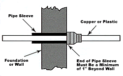
Figure 3
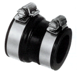
Figure 4
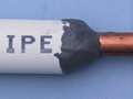
Figure 5
Wrapping
Many municipalities require all underground piping to be encased in a polyethylene encasing wrap or a sleeving material. This material resembles a very long plastic bag and is placed over the tube prior to installation in an open trench, moled or directionally bored hole.
Extreme care must be exercised when ploy type encasing sleeves are used to ensure the poly wrap is not torn or otherwise damaged. Tears in the wrap material can permit unwanted chemicals to collect in the wrap, between the wrap and in the copper tube, which can contribute to premature failure of the tube.
Installation Methods and Considerations
Impact Moling
Impact moling is a trenchless method for the installation of underground piping or conduit systems. A pneumatic machine connected to a steel piercing head (mole) delivers a pulsating burst of air against the mole, which in turn drives the mole through the soil. The mole dimension may vary dependent on the tooling being used, but for most cases, the mole diameter is between 1¾” and 2⅜.”
A hole is excavated to the desired depth and large enough for pneumatic cylinder and steel head (mole) to be placed at the beginning of the moling process. Another hole of like size and depth is excavated at a location where the mole will exit. Once the mole reaches the exit location, it can be withdrawn to the start location. A rope, wire rope or suitable cord is attached to the mole prior to it being withdrawn to the start location. This allows for a suitable pulling cable to be attached to the piping material so that it can then be “pulled” through the slightly oversized hole produced by the mole.
Key Considerations for Impact Moling
While using a moling process for underground copper water services, the following installation conditions should be evaluated on a case-by-case basis to ensure no unforeseen tube damage is encountered.
- Be cognizant of areas that may present different soil conditions in the path of the installation. Where questionable soil conditions are suspected, testing should be conducted to evaluate the soil corrosivity.
- Care should be taken to ensure that sharp rocks, underground structures or other obstacles are not present in the path of installation. Sharp underground objects can gouge, scrape or ultimately damage the copper tube, or poly wrap material, as the tube is pulled through the bore hole.
Mole diameters should be chosen that are as close as possible with the external diameter of the copper tube. An unfilled annular space around the tube can allow for the collection and concentration of ground water that is contaminated with salts or chemicals and can cause corrosion.
Open Trenching
Open trenching is an excavation type of installation for underground piping that has been the industry standard for many years. This method is characterized by an installation that uses any man-made cut, cavity, trench or depression in the earth’s surface formed by earth removal.
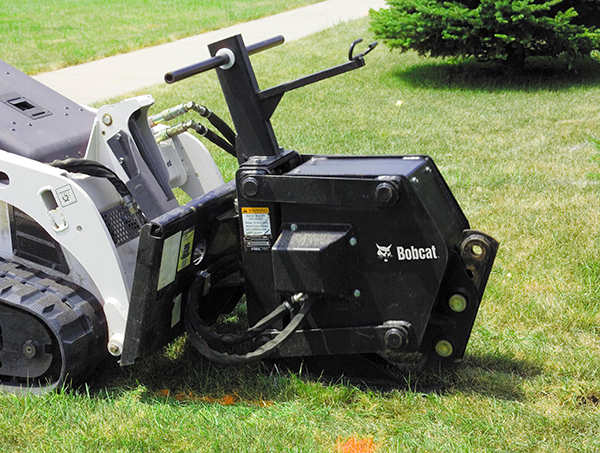
Open trenching can be accomplished by a number of means, although a backhoe or chain type trencher are the most common for water service installations.
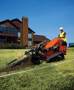
Photo Credit: Charles Machine Works
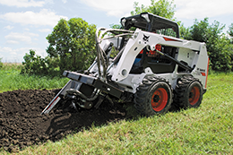
BOBCAT trencher attachment
Key Considerations for Open Trench Installations
When open trenching is utilized for the installation of underground copper tube, a number of factors must be taken into account to ensure it is safe and long lasting.
- All open trenching must meet the minimum requirements of OSHA 2226 Trenching and Excavation Safety.
- Copper tubing should be installed so that it is surrounded by a homogenous backfill on all sides of the tube, including between the trench floor and the bottom of the tube. Laying the tube on the bottom of a trench, where it is in contact with the undisturbed or virgin soil could create an oxygen differential cell along the bottom of the tube and in rare cases can lead to preferential corrosion in this area. Preferred types of backfill include, but are not limited to:
- washed sand
- limestone sand or small limestone chips
- small smooth river stone
- washed pea gravel
Mole diameters should be chosen that are as close as possible with the external diameter of the copper tube. An unfilled annular space around the tube can allow for the collection and concentration of ground water that is contaminated with salts or chemicals and can cause corrosion.
Directional Boring or Drilling
Directional drilling or boring is a process where a wellbore, as they are often referred, can be installed along a given, well-determined lateral distance from vertical or angled starting location. This process is also known as horizontal directional drilling and permits wellbores to be installed along gradual curves as opposed to straight line boring/drilling.
Directional boring or drilling is much like moling with the exception that directional drilling allows for the wellbore to be slightly curved between the starting point and the end-point of the bore. Installation of the water service line is accomplished using the same processes discussed in the moling section above. Examples of directional drilling machines are shown below.
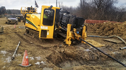
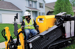
Photos Copyright: VERMEER CORPORATION. All rights reserved.
Key Considerations for Directional Drilling or Boring
The same installation considerations utilized for the moling process should be applied prior to and during any piping installed using directional drilling or boring operations.
Direct Pipe Pulling (Slitting)
In locations and environments where installation of the water service lines will not be affected by low temperatures (freezing) and depth, shallow vibratory direct pulling may be an acceptable option. Soil conditions must be conducive to vibratory plowing.
Vibratory plow type machines can provide the installer the ability to install the service line around obstacles or structures that would preclude the use of open trenching. Vibratory plowing also produces much less damage to lawns as compared to open trenching.
The vibratory plow is inserted into the ground and as the machine moves forward the vibration or oscillation of the blade cuts or separates the ground. Behind the oscillating or vibrating blade, the tube is connected and pulled through the slice in the ground.
BOBCAT vibratory plow attachment
Key Considerations for Direct Pipe Pulling (Slitting)
The same installation considerations utilized for the moling process should be applied prior to and during any piping installed using direct pipe pulling / slitting operations.
Additional trench details can be found in the following two diagrams.
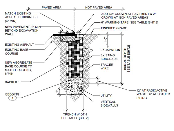
Photo Copyright: Los Alamos National Laboratory Engineering Standards
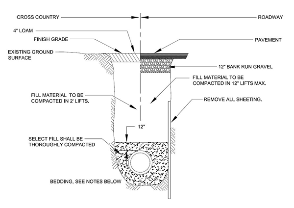
Photo Copyright: Los Alamos National Laboratory Engineering Standards