To achieve high pressure performance, press-connect fittings for HVACR service utilize one, or a combination of several design changes which may include changes in: 1) the o-ring/gasket design or material composition; 2) the wall-thickness of the fitting body; and/or 3) the geometry of the mechanical crimp/press configuration. In many cases, the geometry of the crimp configuration is similar to that for standard, low-pressure press-connect fittings. Though these may require specially designed jaws to accommodate slight changes in geometry or fitting thickness, the installation steps are essentially the same as those shown in the previous section. Care should be taken to ensure that compatible fittings, tools and jaws are utilized and that the fitting manufacturers’ installation instructions are followed.
In other cases, the change in geometry of the higher-pressure HVACR press-connect joint and fitting are quite different than the standard low-pressure press-connect joints, for example to provide a double, 360-degree crimp to one side of the O-ring/gasket. These fittings require the use of specially designed press fittings and crimping jaws to achieve the design pressures of the specific press-connect system (Figure 11.17). These fittings, tools and crimping jaws are not interchangeable with standard low-pressure press-connect systems, so care should be taken to ensure that only the proper, compatible fittings, press jaws and tools are used. Always refer to the manufacturers’ installation instructions. Sample installation instructions are shown here as an example.
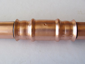 Figure 11.17. Completed joint showing double 360° crimps
Preparation of the tube ends and deburring of the I.D. and O.D. remain the same as that described in the previous installation steps. However, there are a few critical steps that need to be taken to ensure compliance with the fitting manufacturers' minimum installation requirements.
Full depth of insertion into the fitting shall be clearly marked prior to inserting the tube into the fitting (Figure 11.18).
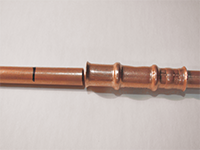 Figure 11.18. Tube marked for insertion into HVACR fitting
Crimping jaw choice and jaw placement prior to crimping are the same as described previously.
Once the pressing process has been completed the jaws can be removed from the fitting and visual examination of the final pressed fitting shall be performed. It is imperative that the tube has remained fully inserted after the pressing process (Figure 11.19).
Figure 11.19. Completed joint with insertion marks visibleAs a quality control check and visual indicator of crimp completion, some manufacturers include or require that the crimping jaws impart a logo or other crimp mark to the fitting as in integral part of the crimping process. In these cases, the completed double 360° crimp shall be inspected for the appropriate crimp mark as prescribed by the fitting manufacturer (Figure 11.20). In this example, the RLS mark that is stamped into the fitting during the pressing process indicates that the proper fitting jaws were used. Other manufacturers may utilize manufacturer-specific markings to indicate compliance with their installation instructions.
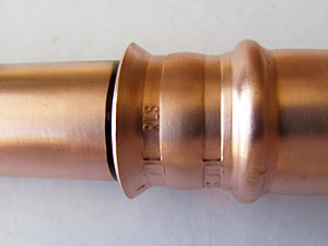 Figure 11.20. Press jaw crimp mark
Fitting manufacturers may also require additional verification steps to ensure proper crimp completion, such as verification of the final crimp dimensions with some type of go-no-go gage, (Figure 11.21, 11.22).
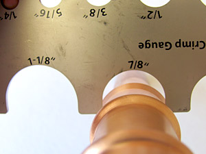 Figure 11.21. Un-crimped or improperly crimped fitting
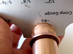 Figure 11.22. Correctly crimped fitting