While copper tube is usually joined by soldering or brazing, there are times when a mechanical joint may be required or preferred. Flared fittings (Figures 9.1 and 9.2) are an alternative when the use of an open flame is either not desired or impractical. Water service applications generally use a flare to iron pipe connection when connecting the copper tube to the main and/or the meter. In addition, copper tube used for Fuel Gas (Liquefied Petroleum (LP), Propane Gas or Natural Gas may be joined utilizing flared brass fittings of single 45º-flare type, according to NFPA 54/ANSI. Z223.1 National Fuel Gas Code. All National Model Codes permit the use of flare joints, but it is important to check with the authority having jurisdiction (AHJ) to determine acceptance for a specific application in any particular jurisdiction.
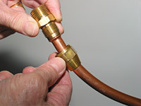 Figure 9.1. Flare Fitting/Flared Joint During Assembly
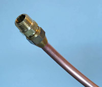 Figure 9.2. Completed Flared Joint
A flare joint should be made with an appropriate tool such as those supplied by a number of tubing/piping tool manufacturers. Make sure to use a tool that matches the outside diameter of the tube being flared and that has the appropriate flare angle, commonly 45º (the physical characteristics of which should be in accordance with the Society of Automotive Engineers SAE J533 Standard - Flares for Tubing). The tool usually consists of flaring bars with openings for various tube sizes and a yoke that contains the flaring cone and a clamp to grip the flaring bars.
When flaring Types L or K copper tube, annealed or soft temper tube should be used. It is possible to flare Types K, L or M rigid or hard temper tube, though prior to flaring it is usually necessary to anneal the end of the tube to be flared. The copper tube must be cut square using an appropriate tubing cutter. After cutting, the tube must be reamed to the full inside diameter leaving no inside burr (Figure 9.3). Tube that is out of round prior to flaring should be resized back to round.
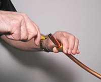 Figure 9.3. Reaming Prior to Flaring the Tube End
Failure to complete either of these steps can, lead to an inadequate seal of the flared joint and, ultimately, to joint failure. Dirt, debris and foreign substances should be removed from the tube end to be flared by mechanical cleaning. This can be accomplished with the use of an abrasive cloth (screen cloth, sand cloth, emery cloth or nylon abrasive cloth).
Now, place a flare nut over the end of the tube with the threads closest to the end being flared. Insert the tube between the flaring bars of the flaring tool in the appropriate opening for the diameter of the tube being flared. Adjust the height of the tube in the opening in accordance with the tool manufacturer's instructions, to achieve sufficient length of the flare. Position the yoke with the flaring cone over the tube end and clamp the yoke in place. Turn the handle of the yoke clockwise (Figure 9.4). This lowers the flaring cone and forces the lip of the tube against the base of the flaring bar to create an angled flare that will mate securely with a corresponding flare-type fitting. Care should be taken not to over-tighten the cone and cause cracking or deformation of the tube and/or the tool. Some tools also provide a setting for ironing or burnishing the flare, as a final step to achieve a more consistent flare. The final flared tube end should have a smooth, even, round flare of sufficient length to fully engage the mating surface of the flare nut without protruding into the threads (Figure 9.5).
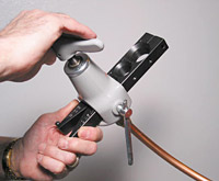 Figure 9.4. Lowering the Flaring Cone Into the Tube End
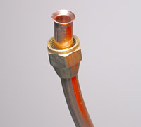 Figure 9.5. Completed Flared Tube End
No material (e.g., pipe joint compound) should be applied to the mating surfaces of the flare fitting and the flared tube end before attaching the flare nut to the fitting body.
How-To: Use Flare Joints for Copper