1. GENERAL INFORMATION ON Cu-Ni ALLOYS
In 1751, A.F. Cronstedt succeeded in isolating nickel. However, Cu-Ni alloys were in existence much earlier, mostly prepared by processing ores. Today, Cu-Ni alloys have gained a variety of interesting applications because of their specific characteristics [1].
Copper and nickel are adjacent to one another in the periodic system of elements, with atomic numbers 29 and 28 and atomic weights 63.54 and 68.71.The two elements are closely related and are completely miscible in both the liquid and solid state. Cu-Ni alloys crystallise over the whole concentration range in a face-centred cubic lattice. The lattice spacing of the face-centre cubic solid solution varies almost linearly with atomic concentration between the values for copper (3.6153 . 10-8cm) and that for nickel (3.5238 . 10-8cm).
Cu-Ni alloys are alloys of copper (base metal with the largest individual content) and nickel with or without other elements, whereby the zinc content may not be more than 1%. When other elements are present, nickel has the largest individual content after copper, compared with each other element.
As with other copper alloys, it is necessary to distinguish between wrought alloys, which are processed to semi-finished products, and cast alloys, from which castings are produced by various casting processes.
Apart from 8.5 to 45% Ni, most commercial alloys usually contain manganese, iron and tin to improve specific properties, cast alloys also have additions of niobium and silicon.
The age-hardenable copper-nickel-silicon alloys with 1.0 to 4.5% Ni and 0.2 to 0.6% Be are not dealt with here. In European standards, these alloys are assigned to ‘low-alloyed copper alloys’ (see CR 13388 and relevant product standards).
 Figure 1. (DKI A 4049) Cu-Ni equilibrium diagram
1.1 Historical
Although elemental nickel was only discovered relatively late on, its use in alloys – without knowledge of the alloy composition – goes back at least two thousand years. This is confirmed by finds of coins from antiquity, which contain up to 10% nickel in addition to copper [2].
The most ancient Cu-Ni coin that has been saved for posterity comes from the period around BC 235. It was found in Bactria and consists of an alloy similar e.g. to the former German 50-Pfennig and 1 DM pieces (approximately 75% Cu and 25% Ni). These and many other old coins are outstanding examples for the high corrosion resistance of Cu-Ni alloys.
In the Middle Ages, Saxon miners gave a mineral, from whose red colour they inferred a copper ore, the nickname ‘coppernickel’ (nickel = goblin = mountain troll). However, they would not succeed in extracting copper from it – a spell was cast on the ore by a ‘nickel’. It was only red nickel pyrites (NiAs), for the veins of ore worked in seams also incorporated copper and iron sulphides as well as arsenides.
In England, the term ‘cupronickel’ was used at the start of the 20th century for an alloy of 80% Cu and 20% Ni. In Germany, the description ‘Cu-Ni alloys’ was in general use for the group of materials containing less than 50% Ni (see 1.).
The Cu-Ni alloys with additions of manganese that are important in electrical engineering were first referred to in 1895 in a paper of the Physikalisch-Technischen Reichsanstalt in Berlin on ‘Electrical properties of Cu-Ni alloys’. Around 1925, it was recognised that additions of iron significantly improve the resistance of Cu-Ni alloys to erosion corrosion in flowing seawater and other aggressive waters.
1.2 The Cu-Ni equilibrium diagram
The equilibrium diagram was first established by Gürtler and Tammann and was later improved by Pilling and Kihlgren, among others. Fig. 1 shows the Cu-Ni equilibrium diagram [3].
Alloys of the two metals form a continuous series of solid solutions having a face-centred cubic lattice, i.e. the Cu-Ni system exhibits complete solubility in both liquid and solid states. The equilibrium diagram is therefore very simple. The melting points of the two components broaden to a melting range in the alloys. The upper curve, which forms the lower boundary of the liquid melt, is called the ‘liquidus’. The curve which forms the upper boundary of the area of a crystals is termed the ‘solidus’. A two-phase area in which liquid and a crystals co-exist is formed between liquidus and solidus.
Below a dotted straight line at the bottom right, behaviour is ferromagnetic, above it is paramagnetic. Thus, for example all alloys up to 80% Ni are paramagnetic at 150 ºC while at 20 ºC alloys containing more than 68.5% nickel exhibit ferromagnetic behaviour.
 Figure 2. (DKI A 4963) Tensile strength and elongation of Cu-Ni alloys as a function of nickel content [4]
 Figure 3. (DKI A 4050) Softening characteristics of a Cu-Ni alloy containing 20% Ni with different manganese additions [1]
1.3 Effect of alloying elements
Nickel has a significant effect on the physical and mechanical properties of Cu-Ni alloys (see 2.). While tensile strength, 0.2% proof strength, hot strength, solidus and liquidus temperature and corrosion resistance increase with nickel content, thermal and electrical conductivity decrease. Tensile strength and elongation are shown in Fig. 2 as a function of nickel content. Tensile strength increases with nickel content, elongation remains almost constant after a slight decrease (up to 5% Ni).
Manganeseis added to the melt for deoxidation. It ties up sulphur, which is detrimental to hot working, as harmless manganese sulphide, improves casting characteristics, increases strength, and especially the softening temperature (Fig. 3).
 Figure 4. (DKI A 4053) Solubility limit of iron for a Cu-Ni alloy containing 10% Ni as a function of temperature [5]
 Figure 5. (DKI A 4054) Effect of iron on variation of hardness of a Cu-Ni alloy containing 10% Ni (specimens quenched from 900 °C and heat treated for 2 h at various temperatures) [6]
Iron – dissolved in the solid solution – increases the corrosion resistance of Cu-Ni alloys. It promotes the formation of an adherent, uniform protective coating in water and thus improves corrosion resistance, primarily in fast-flowing seawater (see 2.3). The solubility of iron in the Cu-Ni solid solution decreases as temperature is lowered (Fig. 4), i.e. these alloys – preferably with higher iron contents - are age-hardenable. The solubility of iron also depends on the nickel content of the alloy, increasing with nickel content to reach a maximum at 30% nickel and falling again as nickel content continues to increase.Fig. 5shows the effect of iron on hardness. Mechanical properties are improved somewhat by iron. Cold workability is slightly worsened.
Tin as an addition element raises tensile strength, tarnish resistance and wear resistance of Cu-Ni alloys. Cu-Ni alloys containing c. 2% Sn are distinguished by very good resistance to stress relaxation and therefore are used a spring materials. Alloys with even higher tin contents (4 to 10%) can also be age-hardened (Fig. 6).
 Figure 6. (DKI A 4964) Age hardening of a Cu-Ni alloy (84.5% Cu, 7.5% Ni, 8% Sn) [7]
Silicon improves the castability of casting alloys and at the same time acts as deoxidant. In the Cu-Ni system, the solubility of silicon increases with nickel content. Up to the solubility limit, increasing silicon contents raise strength and reduce ductility.
Niobium increases tensile strength and proof strength, while elongation drops. The favourable effect of niobium on the weldability of cast alloys is crucial (see 3.6.1).
Lead is kept below 0.02% in wrought alloys intended for hot working. Even lead contents of more than 0.01% impair weldability. However, cast alloys with high lead contents, e.g. in ASTM B 584 from 1 to 11% Pb (C97300 to C97800), are well-known and are used for machining.
Zinc is a main constituent of copper-nickel-zinc alloys (previously ‘nickel silver’ or German silver), which are dealt with in a special DKI information booklet. In contrast, the zinc content of Cu-Ni alloys is restricted to 1% max. Zinc-free alloys are required as materials for fittings in electron tubes to avoid zinc vaporisation.
Titanium promotes the formation of pore-free welds because it can tie up oxygen, hydrogen and nitrogen, due to its high affinity for these gases. Therefore titanium is an essential constituent of welding consumables.
Phosphorus has a strongly embrittling effect in Cu-Ni alloys and decreases weldability (hot shortness and crack formation). Therefore phosphorus content is kept as low as possible, but at most 0.015 to 0.05%.
Furthermore, chromium, aluminium and beryllium are interesting as alloying elements. These additions make Cu-Ni alloys age-hardenable. Chromium increases strength and has a surprisingly favourable effect on resistance to erosion corrosion in fast-flowing seawater and to erosion by solids. Aluminium increases strength, seawater and scaling resistance. Beryllium has the strongest effect on mechanical properties after age-hardening.
The solubility of carbon in nickel (max. 0.18%) is severely reduced as copper content increases – it is about 0.01% with a copper content of 90%. Carbon is not detrimental in Cu-Ni alloys.
Cobalt can often occur as an uncontrolled constituent in Cu-Ni alloys depending on the cobalt content of the nickel used.
Antimony, arsenic, sulphur, tellurium and bismuth are embrittling in small quantities, alone or in combinations, and should not be present in practice in Cu-Ni alloys.
| Material Designation1in accordance with EN | ||
|---|---|---|
| Symbol | Number | Mean composition2(Mass %) |
| CuNi9Sn2 | 2.0875 | 9.5 Ni4; 2.3 Sn; Rem. Cu |
| CuNi10Fe1Mn3 | 2.0872 | 10 Ni4; 1.5 Fe; 0.8 Mn; Rem. Cu |
| CuNi25 | 2.0830 | 25 Ni4; Rem. Cu |
| CuNi30Mn1Fe3 | 2.0882 | 31 Ni4; 0.7 Fe; 1 Mn; Rem. Cu |
| CuNi30Fe2Mn2 | 2.0883 | 30 Ni4; 2 Fe; 2 Mn; Rem. Cu |
| 1In accordance with EN 1412; the same identification symbols are used in ISO 429-1983 2See EN product standards or CR 13388 for precise compositions and permissible impurities 3Where order requirements include welding characteristics: P 0.02% max., S 0.02% max. 4Ni includes 0.5 % Co. |
||
1.4 Cu-Ni alloys in EN and former DIN standards
Wrought Cu-Ni alloys are standardised in different EN standards. Table 1 shows the composition of these alloys. According to the ISO 1190-1, the identification symbol CuNi is applied to wrought Cu-Ni alloys, followed by a number which denotes the mean nickel content. Thus CuNi25 contains approx. 75% Cu and 25% Ni. Further addition elements are indicated in the identification symbol by attaching the chemical symbol and very often by stating the mean contents. Cu-Ni wrought alloys are supplied in the form of strip, sheet, plate, tube, bar, wire and drop forgings (Table 2). Data on mechanical properties are given in the corresponding semi-fabrications standards for the respective alloys.
EN only contains the binary alloy CuNi25. Further binary alloys containing 2, 6 and 10% Ni can be used at application temperatures of 300 to 400ºC max. and are standardised as resistance alloys in DIN 17 471 among others. The standard alloys containing manganese and iron which are also included are characterised by the following chemical symbol for manganese or iron if and insofar as this is necessary for differentiation of similar materials, e.g. CuNi23Mn (23% Ni, 1.5% Mn and therefore about 75.5% Cu), CuNi30Mn (30% Ni, 3% Mn and about 67% Cu) or CuNi44 for the alloy containing 44% Ni, 1% Mn and 55% Cu, in the identification symbol of which only the number of the mean nickel content is stated. The last three materials specified are suitable for maximum application temperatures of 500 to 600ºC.
The composition of Cu-Ni cast alloys standardised in EN 1982 is given in Table 4. EN 1982 also contains characteristic mechanical properties. The number following the identification symbol CuNi represents the mean nickel content. A C with a hyphen is placed afterwards, as the identification symbol for casting alloys – e.g. CuNi10Fe1Mn1-C. Cu-Ni alloys with higher lead contents are standardised in the USA, but not in Germany.
Of the standards which include Cu-Ni alloys, among others, particular mention should be made of EN 12451 (Tubes for condensers and heat exchangers), DIN 1653 (Plate for condensers and heat exchangers), EN 12452 (Tubes with rolled fins for heat exchangers), DIN 74 234 (Hydraulic braking systems, tubes, flanges), DIN 1733 (Welding consumables for copper and copper alloys), DIN 46 460, DIN 46 461, DIN 46 462, and DIN 46 464 (Round wire of resistance alloys) and DIN 46 465 (Flat wire of resistance alloys).
| Symbol | Strip and sheet to EN 1652 | Spring strip to EN 1654 | Cond-enser plates to EN 1653 | Tubes to EN 12 449 | Cond-enser tubes to EN 12 451 and EN 12 452 | Bar to EN 12 163 | Wires to EN 12 1661 | Die forg-ings to EN 12 420 |
|---|---|---|---|---|---|---|---|---|
| CuNi9Sn2 | X | X | X1 | |||||
| CuNi10Fe1Mn3 | X | X | X | X | X | X | ||
| CuNi25 | X | |||||||
| CuNi30Mn1Fe3 | X | X | X | X | X | |||
| CuNi30Fe2Mn2 | X1 | X2 | ||||||
| 1Formerly manufactured according to DIN 17677 to small extent for special purposes. Mechanical properties were not included in the specified standard. 2Only included in EN 12451 |
||||||||
| Identification symbol in accordance with DIN 17471 | Material number | Mean composition (Mass %) |
|---|---|---|
| CuNi2 | 2.0802 | 2 Ni; Rem. Cu |
| CuNi6 | 2.0807 | 6 Ni; Rem. Cu |
| CuNi10 | 2.0811 | 10 Ni; Rem. Cu |
| CuNi23Mn | 2.0881 | 23 Ni; 1.5 Mn; Rem. Cu |
| CuNi30Mn | 2.0890 | 30 Ni; 3 Mn; Rem. Cu |
| CuNi44* | 2.0842 | 44 Ni; 1 Mn; Rem. Cu |
| *This alloy is also standardized in DIN 17 664 as CuNi44Mn1 | ||
1.5 Comparison between related material designations in different countries
The tolerance ranges of the composition of alloys standardised in different countries are not the same as those specified in EN and former national standards in all cases. Therefore Table 5 contains a comparison of the approximately related materials designations for different countries (including ISO) for Cu-Ni alloys.
| Material designation | ||
|---|---|---|
| Symbol | Number | Mean composition (Mass %) |
| CuNi10Fe1Mn1-C2 | CC380H | 10 Ni; 1.5 Fe; 1 Mn; max. 1.0 Nb; max. 0.10 Si; Rem. Cu |
| CuNi30Fe1Mn1-C | CC381H | 30 Ni; 1 Fe; 1 Mn; 0.5 Si; Rem. Cu |
| CuNi30Cr2FeMnSi-C | CC382H | 30 Ni, 2 Cr, 1 Fe, 1 Mn, 0,5 Si, 0,25 Ti, 0,15 Zr |
| CuNi30Fe1Mn1NbSi-C | CC383H | 30 Ni; 1 Fe; 1 Mn; 0.75 Nb; 0.5 Si; Rem. Cu |
| 1A shrinkage value of 1.9 to 2% should be taken into account when making patterns. 2According to former DIN 17658, for weldable castings: % Nb > 1.55 . Si - 0.1 |
||
| Europe EN | Germany DIN | Great Britain BS2 | France NF3 | USA UNS1 | International Stand-ardization ISO4 |
|---|---|---|---|---|---|
| CuNi9Sn2 | CuNi9Sn2 | - | - | C 72500 | CuNi9Sn2 |
| CuNi10Fe1-Mn | CuNi10Fe1Mn | CN 102 | CuNi10Fe1Mn | C 70600 | CuNi10Fe1Mn |
| CuNi25 | CuNi25 | CN 105 | CuNi25 | C 71300 | CuNi25 |
| CuNi30Mn1-Fe | CuNi30Mn1Fe | CN 107 | CuNi30Mn1Fe | C 71500 | CuNi30Mn1Fe |
| CuNi30Fe2-Mn2 | CuNi30Fe2Mn2 | CN 108 | CuNi30Fe2Mn2 | C 71640 | CuNi30Fe2Mn2 |
| CuNi44Mn1 | CuNi44Mn1 | - | CuNi44 | C 72150 | CuNi44Mn1 |
| CuNi10Fe1-Mn1-C | G-CuNi10 | - | - | C 96200 | - |
| CuNi30Fe1-Mn1-C | - | - | ? | - | ? |
| CuNi30Cr2-FeMnSi-C | - | - | ? | - | ? |
| CuNi30Fe1-Mn1NbSi-C | G-CuNi30 | CN 2 | - | C 96400 | G-CuNi30Nb |
| 1UNS = United Numbering System. 2BS = British Standards. 3NF = Norme Franaise 4ISO = International Organisation for Standardization |
|||||
2. PROPERTIES
Cu-Ni alloys have interesting physical properties, good mechanical properties – even under continuous loading and at elevated temperatures – together with high resistance to corrosion in many media – especially seawater.
The properties of the binary Cu-Ni alloys are not adequate for many applications. Certain properties of Cu-Ni alloys can be significantly increased by several additions. Among the addition elements, manganese, iron and tin and niobium and silicon are technically important, also chromium, beryllium and aluminium (see 1.3).
| Symbol EN | Melting range °C |
Electrical conductivity at 20°C (m/Ω . mm2) |
Thermal conductivity at 20°C W/(m . K) | Coefficient of expansion (25 to 300°C) 10-6/K |
Elastic modulus Ε kN/mm2 |
|---|---|---|---|---|---|
| CuNi9Sn2 | 1060-1130 | 6.4 | 48 | 17.6 | 140 |
| CuNi10Fe1Mn3 | 1100-1145 | 5.3 | 46 | 17.0 | 130 |
| CuNi25 | 1150-1210 | 3.1 | 29 | 15.5 | 145 |
| CuNi30Mn1Fe3 | 1180-1240 | 2.7 | 29 | 16.0 | 150 |
| CuNi30Fe2Mn2 | 1160-1240 | 2.0 | 21 | 15.0 | 140 |
| Identification symbol DIN 17471 | Density at 20°C ρ20 kg/dm3 |
Solidus temp °C | Specific heat at 20°C J/(g . K) |
Thermal conductivity at 20°C W/(m . K) |
Mean of coefficient expansion | Thermo-electric voltage versus copper μV/K |
|
|---|---|---|---|---|---|---|---|
| (20 to 100°C) 10-6/K |
(20 to 400°C) 10-6/K |
||||||
| CuNi2 | 8.9 | 1090 | 0.38 | 130 | 16.5 | 17.5 | -15 |
| CuNi6 | 8.9 | 1095 | 0.38 | 92 | 16 | 17.5 | -20 |
| CuNi10 | 8.9 | 1100 | 0.38 | 59 | 16 | 17.5 | -25 |
| CuNi23Mn | 8.9 | 1150 | 0.37 | 33 | 16 | 17.5 | -30 |
| CuNi30Mn | 8.8 | 1180 | 0.40 | 25 | 14.5 | 16 | -25 |
| CuNi44 | 8.9 | 1230-12902 | 0.41 | 23 | 13.5 | 15 | -40 |
| 1See Table 8 for electrical resistivity 2Melting range |
|||||||
2.1 Physical properties
Nickel has a marked effect on the colour of Cu-Ni alloys. The copper colour becomes lighter as nickel is added. Alloys are almost silvery white from about 15% nickel. The lustre and purity of the colour increases with nickel content; from about 40% nickel, a polished surface can hardly be distinguished from that of silver.
| Identification symbol DIN 17471 | Electrical resistivity in Ω . mm2/m | Temperature coefficient of electrical resistance between 20 and 105° C 10-6/K |
Upper appl-ication limit in air °C |
|||||
|---|---|---|---|---|---|---|---|---|
| 20°C | 100°C | 200°C | 300°C | 400°C | 500°C | |||
| CuNi2 | 0.051 | 0.057 | 0.064 | - | - | - | +1000 to +1600 | 300 |
| CuNi6 | 0.101 | 0.107 | 0.114 | 0.123 | - | - | +500 to +900 | 300 |
| CuNi10 | 0.151 | 0.156 | 0.162 | 0.169 | 0.175 | - | +350 to +450 | 400 |
| CuNi23-Mn | 0.302 | 0.308 | 0.315 | 0.323 | 0.331 | 0.339 | +220 to +280 | 500 |
| CuNi30-Mn | 0.402 | 0.404 | 0.410 | 0.417 | 0.424 | 0.432 | +80 to +130 | 500 |
| CuNi44 | 0.492 | 0.49 | 0.49 | 0.49 | 0.49 | 0.49 | -80 to +40 | 600 |
| 1Allowable deviation 10% 2Allowable deviation 5% |
||||||||
The important physical properties of the wrought Cu-Ni alloys standardised in EN are summarised in Table 6 and those of the Cu-Ni resistance alloys standardised in DIN 17 471 are shown in Table 7.
The density of copper (8.93 kg/dm3at 20 °C) varies only slightly with increasing nickel content (density of nickel at 20 °C = 8.9 kg/dm3) and is 8.9 kg/dm3 for all Cu-Ni alloys specified in DIN 17 664. This aspect can also be seen in Table 7 with the physical properties of the Cu-Ni resistance alloys to DIN 17 471. The high thermal conductivity of pure copper of 394 W/(m.K) is severely reduced by nickel (Fig. 7); it reaches a minimum of c. 21 W/(m.K) at about 45% Ni. The coefficient of linear expansion initially decreases sharply with addition of nickel, then more slowly (Fig. 8). The specific heat (at 20 °C) of copper is 0.385 J/(g.K) and of nickel is 0.452 J/(g. K). As nickel content increases, it first diminishes slightly and a mean value of 0.377 J/(g.K) can be expected.
 Figure 7. (DKI A 4055) Thermal conductivity of Cu-Ni alloys at 20 °C as a function of nickel content [1]
 Figure 8. (DKI A 4056) Mean coefficient of linear expansion of Cu-Ni alloys as a function of nickel content [1]
The electrical resistivity of Cu-Ni resistance alloys at different temperatures is shown in Table 8. It rises steeply with nickel content, so that Cu-Ni alloys are suitable as resistance materials. A maximum occurs at c. 45% Ni. The minimum of the temperature coefficient of electric resistance is in approximately the same concentration range.
 Figure 9. (DKI A 4057) Electrical resistivity and temperature coefficient of electrical resistance of Cu-Ni alloys as a function of nickel content [1]
The high thermoelectric power of Cu-Ni alloys in the range between 40 and 50% Ni is particularly noteworthy compared with other metals such as iron (Fig. 10), copper, platinum etc. They are therefore especially suitable for use in thermocouples for temperature measurements in a moderate temperature range. Fig. 11 shows the thermoelectric power of CuNi44 versus copper and iron as a function of temperature. The high thermoelectric force of CuNi44 excludes its use as resistance material in low-voltage appliances, because the copper connections to CuNi44 form a thermocouple.
 Figure 10. (DKI A 4058) Thermoelectric power of Cu-Ni alloys versus iron at 816 °C as a function of nickel content [1]
 Figure 11. (DKI A 4059) of CuNi44 versus copper and iron (basic values of thermoelectric force in accordance with DIN 43 710) [6]
The elastic modulus (see Table 6) increases with nickel content (CuNi10FeMn: 130 kN/mm2; CuNi44Mn1: 165 kN/mm2).
Cu-Ni alloys do not exhibit any ferromagnetism. Copper is diamagnetic, nickel is ferromagnetic. Nickel-copper alloys change from diamagnetic via paramagnetic to ferromagnetic as nickel content increases. Depending on the alloy, iron has a small effect when it is present in solid solution. If iron is precipitated, these ferromagnetic microscopic particles lead to a macroscopic increase of ferromagnetism.
The precipitate-free matrix remains diamagnetic or paramagnetic. Cu-Ni alloys containing 20 to 25% Ni and 20% Fe or about 25% Co are pronounced magnetic materials. As a result of their high remanence and coercive force, they are also suitable for permanent magnets.
All physical properties of the two wrought Cu-Ni alloys CuNi10Fe1Mn and CuNi30Mn1Fe have been investigated thoroughly and are well known from room temperature to 1000°C [8].
Some physical properties of Cu-Ni casting alloys to DIN 1982 are shown in Table 9.
2.2 Mechanical properties
| Symbol | Melting range °C | Electrical conductivity at 20°C m/( Ω . mm2) |
Thermal conductivity at 20°C W/(m . K) |
Coefficient of expansion (25 to 300°C) 10-6/K |
Elastic modulus Ε kN/mm2 |
|---|---|---|---|---|---|
| CuNi10Fe1Mn1-C | 1105-1140 | 5.5 | 59 | 17 | 123 |
| CuNi30Fe1Mn1NbSi-C | 1170-1240 | 2.5 | 29 | 16 | 145 |
| 1Density of both materials is 8.9 kg/dm3 | |||||
2.2.1 Mechanical properties at room temperature
2.2.1.1 Wrought Cu-Ni alloys
Table 10 contains characteristic mechanical properties for wrought Cu-Ni alloy sheet and strip conforming to EN 1652. Further data are given in the respective semi-fabricated product standards. Material condition is indicated in the mechanical property standards by adding the letter R to the alloy identification symbol, with a following number, e.g. CuNi10Fe1Mn R320. A tensile strength of at least 320 N/mm2is guaranteed for the strength level R320. The 0.2% proof stress and elongation are also defined by the strength level. A minimum hardness (Vickers hardness) is guaranteed by adding the letter H with a following number, e.g. CuNi19Fe1Mn H100.
Table 11 shows the tensile strength and elongation of Cu-Ni resistance alloys.
| Symbol | Number | Thick mm | Tensile strength Rm N/mm2 | 0.2% Proof stress Rp0.2 N/mm2 | Elongation | Vickers hardness HV | ||
|---|---|---|---|---|---|---|---|---|
| A50mmfor thickness up to 2.5 mm %min. |
A for thickness above 2.5 mm %min. |
|||||||
| CuNi9Sn2 | R340 | CW351H | 0.2 to 5 | 340 to 410 | (max. 250) | 30 | 40 | - |
| H075 | - | - | - | - | 75 to 110 | |||
| R380 | 0.2 to 5 | 380 to 470 | (min. 200) | 8 | 10 | - | ||
| H110 | - | - | - | - | 110 to 150 | |||
| R450 | 0.2 to 2 | 450 to 530 | (min. 370) | 4 | - | - | ||
| H140 | - | - | - | - | 140 to 170 | |||
| R500 | 0.2 to 2 | 500 to 580 | (min. 450) | 2 | - | - | ||
| H160 | - | - | - | - | 160 to 190 | |||
| R560 | 0.2 to 2 | 560 to 650 | (min. 520) | - | - | - | ||
| H180 | - | - | - | - | 180 to 210 | |||
| CuNi10-Fe1Mn | R300 | CW352H | 0.3 to 15 | min. 300 | (min. 100) | 20 | 30 | - |
| H070 | - | - | - | - | 70 to 120 | |||
| R320 | 0.3 to 15 | min. 320 | (min. 200) | - | 15 | - | ||
| H100 | - | - | - | - | min. 100 | |||
| CuNi25 | R290 | CW350H | 0.3 to 15 | min. 290 | (min. 100) | - | - | - |
| H070 | - | - | - | - | 70 to 100 | |||
| CuNi30-Mn1Fe | R350 | CW354H | 0.3 to 15 | 350 to 420 | (min. 120) | - | 35 | - |
| H080 | - | - | - | - | 80 to 120 | |||
| R410 | 0.3 to 15 | min. 410 | (min. 300) | - | 14 | - | ||
| H110 | - | - | - | - | min. 110 | |||
| Identification symbol | Tensile strength1Rm N/mm2min. | Elongation (Lo = 100 mm) A % for nominal diameter in mm | ||||
|---|---|---|---|---|---|---|
| 0.02 to 0.0632 | >0.063 to 0.1252 | >0.125 to 0.52 | >0.5 to 1 | >13 | ||
| CuNi2 | 220 | - | approx. 15 | approx. 18 | ≥18 | ≥25 |
| CuNi6 | 250 | - | approx. 15 | approx. 18 | ≥18 | ≥25 |
| CuNi10 | 290 | - | approx. 15 | approx. 20 | ≥20 | ≥25 |
| CuNi23Mn | 350 | approx. 12 | approx. 18 | approx. 20 | ≥20 | ≥25 |
| CuNi30Mn | 400 | approx. 12 | approx. 18 | approx. 20 | ≥20 | ≥25 |
| CuNi44* | 420 | approx. 12 | approx. 18 | approx. 20 | ≥20 | ≥25 |
| 1Values are applicable to wire with diameter more than 2 mm; values are substantially higher for smaller diameters. Values also apply to flat wire and strip whose thickness is equal to diameter. 2Only guide values. 3Measurement length Lo can be agreed for wire diameters more than 3 mm. |
||||||
Fig. 12 shows the increase of tensile strength, 0.2% proof stress and hardness with nickel content. There is only a relatively small drop in elongation and reduction of area with the rise in tensile strength. On the other hand, hardness increases strongly with nickel content. The notched-bar impact toughness is only slightly affected by nickel content.
 Figure 12. (DKI A 4060) Mechanical properties of Cu-Ni alloys as a function of nickel content (determined on laboratory-melted specimens): specimens heat treated as 600 °C; notched impact toughness specimens forged as 1100 to 800 °C [1]
Iron has a favourable effect on the mechanical properties of Cu-Ni alloys. Fig. 13 shows this with an example of an alloy containing 10% Ni. Additional improvements of the mechanical properties of CuNi30Mn1Fe are obtained by increasing the iron and manganese contents each to 2%; thus, for example, strip and sheet of the alloy CuNi30Fe2Mn2have a tensile strength of 440 N/mm2and a 0.2% proof stress of 145 N/mm2.
 Figure 13. (DKI A 4065) Effect of iron content on the mechanical properties of a Cu-Ni alloy containing 10% Ni. Specimens quenched from 900 °C were heat treated for 2 h to obtain the hardness maximum [9]
Additions of aluminium or chromium, for example, produce a further strength increase; Table 12 contains two materials with improved mechanical properties.
As with all metallic materials, tensile strength, 0.2% proof stress and hardness increase with increasing cold deformation of wrought Cu-Ni alloys, while elongation decreases (Fig. 14).
 Figure 14. (DKI A 4965) Work hardening characteristics of CuNi9Sn2 [10]
 Figure 15. (DKI A 1219) Mechanical properties of a Cu-Ni alloy containing 20% Ni at low temperatures. Specimen cross section 16 x 14.8 mm [6]
2.2.1.2 Cu-Ni cast alloys
Table 13 contains mechanical properties of Cu-Ni cast alloys conforming to DIN 17 658.
Three age-hardenable Cu-Ni casting alloys with additions of aluminium, chromium or beryllium (Table 14) must also be mentioned. The alloy with 2% Al can be used in the as-cast state or age-hardened. The largest increase of strength is achieved by adding beryllium – after age hardening. An alloy of this type is already in use in the USA for seawater applications.
High-strength age-hardenable Cu-Ni casting alloys containing up to 6% tin, usually with further additions such as lead and zinc, are standardised in ASTM 584.
2.2.2 Mechanical properties at low temperatures
Like other copper alloys, Cu-Ni alloys possess excellent mechanical properties at low temperatures, which are shown for an alloy containing 20% Ni in Fig. 15. Here tensile strength decreases with falling temperature without a marked reduction of elongation and reduction of area. Thus these alloys exhibit no embrittlement at low temperatures. They are therefore very suitable for applications in cryogenic engineering.
| Addition of | Mean composition (Mass %) | Material condition | Tensile strength Rm N/mm2 | 0.2% Proof stress Rp0.2 N/mm2 | Elongation A5 % | Brinell hardness. HB |
|---|---|---|---|---|---|---|
| Al | 5 Ni; 4 Al; 0.8 Cr; 2.5 Mn; Rem. Cu | Soft | 450 to 550 | 170 to 230 | 35 to 50 | 110 to 130 |
| Age-hardened | 1000 to 1090 | 940 to 1040 | 1 to 3 | 320 to 340 | ||
| Cr | 30 Ni; 3 Cr; 0.5 Fe; 0.5 Mn; Rem. Cu | Age-hardened | 590 | ≥360 | 27 | 110 |
| Symbol | Form supplied | Supplement. | Tensile strength Rm N/mm2min. | 0.2% Proof stress Rp0.2 N/mm2min. | Elongat. A % min. | Brinell hard. HB min. | Elastic modulus E KN/mm2approx.1 |
|---|---|---|---|---|---|---|---|
| CuNi10-Fe1Mn1-C | Sand casting | -GS | 280 | 120 | 20 | 70 | 1231 |
| Centri-fugal casting | -GZ | 280 | 100 | 25 | 70 | - | |
| Contin-uous casting | -GC | 280 | 100 | 25 | 70 | - | |
| CuNi30-Fe1Mn1-C | Sand casting | -GS | 340 | 120 | 18 | 80 | - |
| Centri-fugal casting | -GC | 340 | 120 | 18 | 80 | - | |
| CuNi30Cr2-FeMnSi-C | San casting | -GS | 440 | 250 | 18 | 115 | - |
| CuNi30Fe1-Mn1NbSi-C | Sand casting | -GS | 440 | 230 | 18 | 115 | 1451 |
| 1according to former DIN 17658 | |||||||
| Addition of | Mean composition (Mass %) | Material condition | Tensile strength Rm N/mm2 | 0.2% Proof stress Rp0.2 N/mm2 | Elongation A5 % |
|---|---|---|---|---|---|
| Al | 14 Ni; 10 Mn; 5 Fe; 2 Al; Rem. Cu | As cast | 460 | 260 | 35 |
| Heat treated | 460 to 620 | 310 to 420 | 20 to 40 | ||
| Cr | 30 Ni; 2 Cr; 1 Mn; 1 Fe; 0.5 Si; Rem. Cu | As cast | 520 to 580 | 330 to 380 | 22 |
| Be | 30 Ni; 1 Fe; 1 Mn; 0.5 Be; Rem. Cu | Heat treated | 750 to 850 | 520 to 620 | 7 to 24 |
2.2.3 Mechanical properties at elevated temperatures
Cu-Ni alloys retain good mechanical properties at elevated temperatures.
2.2.3.1 Hot strength
The hot strength of copper increases with only a small addition of nickel. The effect of nickel on the softening of cold-rolled Cu-Ni alloys at elevated temperatures is shown in Fig. 16. By adding iron, mechanical properties are improved, not only at room temperature, but also at elevated temperatures. Fig. 17 shows this with an example of an alloy containing 10% Ni. CuNi10Fe1Mn, for example, can be used in pressure vessel construction up to 300°C, CuNi30Mn1Fe up to 350°C. Above these limit temperatures, strength drops markedly, particularly the creep strength and creep strain limit (see 2.2.3.2).
 Figure 16. (DKI A 4063) Softening of Cu-Ni alloys as a function of annealing temperature and of nickel content (specimens cold rolled 50% before annealing) [1]
 Figure 17. (DKI A 4066) Softening of Cu-Ni alloy containing 10% Ni as a function of iron content and of temperature (annealing time 2 h). Specimens quenched from 900 °C were cold rolled 50% [9]
Values for the elastic modulus decrease as temperature increases by about 50-100 N/mm2per °C.
2.2.3.2 Creep behaviour
Metallic materials are not infrequently exposed to continuous loading at elevated temperatures, so that knowledge of the creep behaviour of Cu-Ni alloys is necessary. The creep test gives values in this respect. It is used to determine material behaviour under static loading (creep loading) under conditions in which the time under stress has a substantial effect in addition to the stress level and the temperature, thus the term ‘creep behaviour’.
The creep rupture strength at a specific temperature is the static load (at test temperature) referred to the initial cross section of the test pieces at room temperature which causes fracture of the test piece after a specific time has elapsed. That maximum load which a workpiece (test piece) can withstand without fracture ‘for an infinitely long time’ is called the creep strength. The creep limit at a specific temperature is then that load which gives rise to a specific permanent strain after a specific time (and at the test temperature).
Values for creep strength and 1% creep limit for alloys CuNi10Fe1Mn and CuNi30Mn1Fe which determine the limit temperatures for the use of these alloys under long-term loading are given in Table 15.
 Figure 18. (DKI A 4966) Softening of CuNi30Mn1Fe [12]
| Temp. °C | Alloy CuNi10Fe1Mn2 | |||||||
|---|---|---|---|---|---|---|---|---|
| Creep strength in N/mm2for time [h] | 1% Creep limit in N/mm2for the time [h] | |||||||
| 100 | 1000 | 10 000 | 100 000 | 100 | 1000 | 10 000 | 100 000 | |
| 20 | - | - | - | - | - | 123 | 116 | - |
| 300 | 239 | 212 | 172 | (121) | - | 105 | (93) | - |
| 350 | 194 | 143 | 91 | ( 55) | - | 108 | 65 | - |
| 400 | 121 | 73 | 41 | - | - | 76 | 45 | - |
| 450 | - | - | - | - | - | - | - | - |
| 500 | - | - | - | - | - | - | - | - |
| 550 | - | - | - | - | - | - | - | - |
| 600 | - | - | - | - | - | - | - | - |
| Temp. °C | Alloy CuNi30Mn1Fe3 | |||||||
|---|---|---|---|---|---|---|---|---|
| Creep strength in N/mm2for time [h] | 1% Creep limit in N/mm2for time [h] | |||||||
| 100 | 1000 | 10 000 | 100 000 | 100 | 1000 | 10 000 | 100 000 | |
| 20 | - | - | - | - | - | - | - | - |
| 300 | - | - | - | - | - | - | - | - |
| 350 | (391) | (363) | (326) | - | 361 | 317 | (258) | - |
| 400 | 351 | 305 | 244 | - | 299 | 232 | (166) | - |
| 450 | 292 | 221 | 153 | - | 211 | 145 | (97) | - |
| 500 | 208 | 139 | 92 | - | 138 | 87 | (50) | - |
| 550 | 133 | 85 | 50 | - | 83 | 44 | (14) | - |
| 600 | 84 | 46 | 18 | - | 44 | 12 | - | - |
| 1Values in brackets are extrapolated 2Material condition: annealed 3Material condition: cold rolled, 40% |
||||||||
2.2.4 Fatigue limit
Since many components are subjected to an oscillating load, the fatigue limit, called fatigue strength for short, is an important characteristic quantity for practical application. In contrast to creep behaviour (see 2.2), it is defined as the maximum stress amplitude oscillating about a given mean stress which can be withstood by a workpiece (test piece) ‘infinitely often’ without fracture and without unacceptable deformation.
Copper alloys do not have any pronounced limit value of stress but a steady fall in strength is observed with increasing number of load cycles followed by an imperceptibly small drop in the area of high load cycles. Fatigue strengths at high load cycles (c. 108) are stated as fatigue limits.
Table 16 summarises fatigue limit values for CuNi10Fe1Mn. CuNi25, CuNi30Mn1Fe and CuNi44Mn1 for 108load cycles [13].
| Alloy | Fatigue strength in N/mm2for 108load cycles |
|---|---|
| CuNi10Fe1Mn1 | 150 |
| CuNi252 | 275 |
| CuNi30Mn1Fe3 | 245 |
| CuNi44Mn14 | 290 |
| 1No data on material form, cold rolled. 2Wire (2 mm dia.), cold work: 88%. 3Bar (14 mm dia.), cold drawn (33%). 4Bar, cold drawn and stress-relief heat-treated. |
|
2.3 Corrosion resistance
Cu-Ni alloys are among the corrosion-resistant copper alloys. They are resistant to moisture, non-oxidising acids, alkalis and salt solutions, organic acids and to gases such as oxygen, chlorine, hydrogen chloride, hydrogen fluoride, sulphur dioxide and carbon dioxide. There is no risk of stress corrosion cracking with them, the tendency to selective corrosion is extremely small and pitting corrosion is seldom observed. The resistance of these alloys – as with the Cu-Al alloys – relates to a stable protective coating on the surface due to the alloying metal.
| Iron content % | Semi-fabricated form | Corrosion rate in g/m2at a flow rate in m/s of | |||
|---|---|---|---|---|---|
| 3 | 4.12 | 6.1 | 8.23 | ||
| 0.04 | Tube | 27.5 | 35.5 | ||
| 0.49 | 2.2 | 2.7 | |||
| 0.03 | Bar | 24.7 | 22.9 | ||
| 0.48 | 2.5 | 3.2 | |||
Since copper and nickel form a continuous series of solid solutions, no heterogeneous structure can occur in these alloys. Alloys containing 10% and 30% Ni have good resistance even to hot seawater and at high flow rates. Thus these alloys are stable up to moderate flow rates of 6 m/s. It is necessary to maintain a minimum flow rate of 0.6 m/s to avoid corrosion problems. Rates are guide values.
The manganese-containing alloys CuNi44Mn1 and CuNi30Mn1Fe, as materials for electrical resistors, are scarcely attacked by dilute acids, more strongly by acid vapours – in particular hydrochloric acid vapours. They have good resistance to ammonia-containing air. The resistance of these resistance alloys to different atmospheres is given in DIN 17 471. In addition, CuNi44Mn1 is also resistant to alkali metals up to about 600 °C. Of the iron-containing wrought alloys, CuNi10Fe1Mn contains 0.5 to 1.0% Mn and 1.0-2.0% Fe and CuNi30Mn1Fe 0.5 to 1.5% Mn and 0.4-1.0% Fe (see Table 1). Iron contents at this level substantially improve the adherence of protective coatings against corrosion and thus markedly increase resistance to erosion corrosion, especially in seawater and other aggressive waters, e.g. brackish and mine waters. When iron contents are in this optimum range, copper alloys also do no not show any selective corrosion. Iron contents that are too low reduce the resistance to erosion in flowing seawater, excessive iron contents reduce resistance to deposit corrosion in static seawater. The importance of iron for the seawater resistance of CuNi30Mn1Fe can be seen in Fig. 19 and Table 17. CuNi30Mn1Fe is also resistant to ammoniacal condensates. By increasing each of the iron and manganese contents in the 30% Ni alloy to 2% (see CuNi30Fe2Mn2 in Table 1), mechanical wear by solids contained in cooling water (e.g. sand) is further reduced.
The tarnish resistance of Cu-Ni alloys is additionally increased by tin (see 1.3). Resistance to fast-flowing seawater in particular can be increased still further by addition of chromium; aluminium contents have a favourable effect on corrosion and scaling resistance of wrought and cast Cu-Ni alloys.
Table 18 contains some comparable data on the behaviour of Cu-Ni alloys towards various agents.
| Acetone | 1 | Iron(III) sulphate | 4 | Magnesium chloride | 2 | Nitric acid | 4 |
| Alcohol1) | 1 | Iron(III) chloride | 2 | Magnesium hydroxide | 1 | Hydrochloric acid, dry | 2 |
| Aluminium chloride | 2 | Iron(III) sulphate | 2 | Magnesium sulphate | 1 | Sulphur, solid | 1 |
| Aluminium sulphate | 1 | Natural gas | 1 | Molasses1) | 1 | Sulphur chloride, dry | 1 |
| Formic acid | 2 | Vinegar1) | 1 | Milk1) | 1 | Sulphur dioxide, dry | 1 |
| Ammonia, dry | 1 | Acetic acid (20-50%)1) | 1 | Lactic acid | 1 | Sulphur dioxide, wet | 3 |
| Ammonia, wet | 3 | Acetic acid ester | 1 | Sulphur trioxide, dry | 1 | ||
| Ammonium chloride | 3 | Sodium carbonate | 1 | Sulphuric acid (less than 78%) | 2 | ||
| Ammonium hydroxide | 3 | Boiled oil | 1 | Sodium bisulphate | 1 | Sulphuric acid (more than 78%) | 3 |
| Ammonium nitrate | 3 | Fluorosilicic acid | 2 | Sodium chloride | 1 | Seawater | 1 |
| Ammonium sulphate | 2 | Hydrofluoric acid | 2 | Sodium cyanide | 4 | Soap solution | 1 |
| Aniline and aniline dyes | 1 | Formaldehyde | 1 | Sodium hydroxide | 1 | Stearic acid | 1 |
| Asphalt | 1 | Freon | 1 | Sodium hypochlorite | 2 | ||
| Ether | 1 | Furfural | 1 | Sodium carbonate | 1 | Turpentine | 1 |
| Ethylene glycol | 1 | Sodium nitrate | 1 | Carbon tetrachloride, dry | 1 | ||
| Acetylene2) | 4 | Gelatine1) | 1 | Sodium peroxide | 2 | Carbon tetrachloride, wet | 1 |
| Tannic acid | 1 | Sodium phosphate | 1 | Toluene | 1 | ||
| Barium chloride | 2 | Drinks containing. carbonic acid1) | 1 | Sodium silicate | 1 | Trichlorethylene, dry | 1 |
| Barium sulphate | 1 | Glucose1) | 1 | Sodium sulphate | 1 | Trichlorethylene, wet | 1 |
| Cotton seed oil | 1 | Glycerol | 1 | Sodium sulphide | 1 | ||
| Petrol | 1 | Sodium thiosulphate | 1 | Water, acidic mine water | 3 | ||
| Benzene | 1 | Heating oil | 1 | Sodium chloride | 3 | Water, condensate | 1 |
| Beer1) | 1 | Sodium sulphate | 3 | Water, drinking water | 1 | ||
| Boric acid | 1 | Potassium chloride | 1 | Hydrogen | 1 | ||
| Butane | 1 | Potassium cyanide | 4 | Oleic acid | 2 | Hydrogen peroxide | 2 |
| Potassium hydroxide | 1 | Oxalic acid | 1 | Tartaric acid | 1 | ||
| Calcium bisulphate | 2 | Potassium sulphate | 1 | Whisky | 1 | ||
| Calcium chloride (acid) | 2 | Carbon dioxide, dry | 1 | Phosphoric acid | 2 | ||
| Calcium chloride (basic) | 2 | Carbon dioxide, wet1) | 1 | Picric acid | 4 | Zinc chloride | 2 |
| Calcium hydroxide | 1 | Creosote | 1 | Propane | 1 | Zinc sulphate | 1 |
| Calcium hypochlorite | 2 | Copper sulphate | 1 | Citric acid1) | 1 | ||
| Chlorine, dry | 1 | Mercury | 4 | Sugar beet syrup1) | 1 | ||
| Chlorine, wet | 2 | Paint | 1 | Mercury salts | 4 | ||
| Chromic acid | 4 | Paint thinners | 1 | ||||
| Glue | 1 | Raw sugar syrup1) | 1 | ||||
| Iron(III) chloride | 4 | Linseed oil | 2 | ||||
| 1Tinning is necessary in the drinks and foods industry 2There is a risk of explosion due to the formation of copper acetylide 31 = very good resistance; 2 = resistant; 3 = acceptable; 4 = not recommended |
|||||||
| Identification symbol | Castability | Working | |
|---|---|---|---|
| Cold | Hot | ||
| WroughtCu-Ni alloys to EN | |||
| CuNi9Sn2 | good | v. good | |
| CuNi10Fe1Mn | good | v. good | |
| CuNi25 | good | good | |
| CuNi30Mn1Fe | good | good | |
| CuNi30Fe2Mn2 | good | good | |
| CuNi44Mn11 | good | good | |
| CastCu-Ni alloys to EN 1982 | |||
| CuNi10Fe1Mn1-C | good | ||
| CuNi30Fe1Mn1 NbSi-C | good | ||
| Identification symbol | Joining | Surface treatment | |||||||
|---|---|---|---|---|---|---|---|---|---|
| Welding | Soldering and brazing | Mechanical polishing | Electrochemical polishing | ||||||
| Gas | Metal arc | Gas-shielded | Resistance | Brazing | Soldering | ||||
| WroughtCu-Ni alloys to EN | |||||||||
| CuNi9Sn2 | poor | good | v. good | v. good | v. good | v. good | v. good | good | good |
| CuNi10Fe-1Mn | poor | good | v. good | v. good | v. good | v. good | v. good | good | good |
| CuNi25 | poor | v. good | v. good | v. good | v. good | v. good | v. good | v. good | good |
| CuNi30Mn-1Fe | poor | v. good | v. good | v. good | v. good | v. good | v. good | good | good |
| CuNi30Fe-2Mn2 | v. good | v. good | v. good | v. good | v. good | v. good | good | good | |
| CuNi44Mn11 | v. good | v. good | v. good | v. good | v. good | v. good | good | good | |
| CastCu-Ni alloys to EN 1982 | |||||||||
| CuNi10Fe-1Mn1-C | poor | v. good | v. good | v. good | v. good | v. good | v. good | good | good |
| CuNi30Fe-1Mn1 NbSi-C | poor | v. good | v. good | v. good | v. good | v. good | v. good | good | good |
| 1as standardized in DIN 17471 | |||||||||
 Figure 19. (DKI A 4051) Effect of iron on the resistance of CuNi30Mn1Fe condensers in seawater. Flow rate 6 m/s; water temperature 32 °C [1]
3. MANUFACTURE AND PROCESSING
Table 2 shows the semi-fabricated forms in which standard wrought Cu-Ni alloys can be supplied. Table 19 gives information on the processing of wrought Cu-Ni alloys to EN and cast alloys to EN 1982.
3.1 Melting
 Figure 20. (DKI A 2586) Solubility of hydrogen in Cu-Ni alloys [1]
Cu-Ni alloys exhibit a very strong tendency to absorb gases as nickel content and temperature increase. It is known that the solubility for hydrogen and oxygen rapidly decreases during the transition to the solid state and pores and blowholes then occur, since the gases usually cannot escape. Hydrogen solubility is shown as a function of nickel content and temperature in Fig. 20.
Absorption of hydrogen is largely avoided by oxidising or neutral melting practices. These necessitate action to ensure the melt is kept free from carbon. When an oxidising melting practice is followed, a final deoxidation with copper-manganese (V-CuMn30) or lithium is required. Hydrogen can be reliably removed during neutral melting by treatment with a scavenging gas, e.g. with dry nitrogen. A neutral cover agent is used in neutral melting practice. Carbon-containing covering agents, e.g. charcoal, must be avoided.
3.2 Casting
Casting temperatures are approximately 100 to 200°C above the liquidus, depending on the dimensions and weight of castings. When making moulds, a shrinkage allowance of about 2% should be taken into account.
Cu-Ni alloys can be cast by sand, permanent mould, continuous or centrifugal casting processes. Shaped castings are made in dry sand moulds of medium permeability. Formats are cast in cast iron or water-cooled copper moulds. Casting shaped parts of Cu-Ni alloys is not simple and makes high demands of the foundryman.
3.3 Working
Hot working (rolling, extruding, forging etc.) is carried out in the semi-fabricating plant after preheating in sulphur-free atmosphere. The hot workability of Cu-Ni alloys is not substantially affected by manganese and iron (see Table 19). On the other hand, quite small additions of certain elements have a crucial effect on hot workability [15]. Hot working takes place between 850 and 1100°C.
Cold working does not present any problems. A Cu-Ni alloy e.g. containing 20% Ni can be cold worked 95% without intermediate annealing. Alloys with smaller nickel contents have proportionately good cold workability. The best deep drawability is possessed by binary Cu-Ni alloys containing 15 to 20% Ni.
3.4 Heat treatment
In general, heat treatments are only used with Cu-Ni alloys for soft annealing and stress relieving. Temperatures for recrystallisation annealing can vary over wide limits between about 620 and 900 °C, depending on degree of cold work, nickel content and additional constituents. High temperatures are associated with short annealing times (continuous annealing) and low temperatures with long annealing times (static annealing). Stress-relief annealing is carried out at 280 to 500 °C. It is advisable to anneal excluding air or in a slightly reducing atmosphere, to avoid the pickling that is required with air-containing annealing atmospheres. Sulphur-containing furnace atmospheres must not be used. The workpiece must be degreased before annealing, to prevent its surface being contaminated with sulphur and/or carbon.
Some Cu-Ni alloys can be age-hardened by heat treatment. Thus e.g. (non standardized) the chromium-containing wrought alloy CuNi30Cr (see Table 12) and the cast alloy CuNi30Cr2MnSi-C are always age-hardened during (slow) cooling from the processing temperature (hot working or casting) at temperatures around 500°C.
The aluminium-containing wrought alloy CuNi5Al4Mn2 (see Table 12) is usually age-hardened at 300 to 400°C with a holding time of 0.5 to 2 h. The material is soft annealed by heating for a few minutes at above 840°C and fast cooling, either in an air stream or in water.
3.5 Machining
Homogeneous Cu-Ni alloys are difficult to machine. As a result of their great toughness, their machinability is poor, especially in the soft condition. They form long, ductile chips, so that chip removal frequently presents problems and, as a result, there is a negative effect on the surface quality that can be obtained. It is necessary to ensure that the long chips can be released smoothly, to avoid snarl-ups. The high-alloy wrought alloys and the cast alloys can be machined more easily than the alloys with low nickel contents. Machinability is not improved by manganese and iron.
With regard to their machinability, copper alloys can be roughly divided into three main groups [16]. This puts Cu-Ni alloys into group III (moderate to poor machinability). The strength condition is definitive for a further sub-division within this group. Half-hard and hard material is more machinable than soft grades, since chips break more easily with the harder grades. This is often obtained at the cost of somewhat short tool lives. Guidance for machining is given in the reference cited above. Chip-breaking additions such as sulphur or lead are not normally made to Cu-Ni alloys, because of their very detrimental effect on hot workability.
In general, hard metals are preferred for tools; they have longer service lives than high-speed steels and the risk that jammed chips will prematurely damage the cutting edge is smaller. Medium feeds and cutting speeds should be chosen; thorough cooling by drilling emulsions or sulphur-free oils is advisable.
Lead-containing cast Cu-Ni alloys, such as are standard in the USA, have appreciably better machinability.
3.6 Joining
Generally, there are no problems in welding or soldering and brazing Cu-Ni alloys. Adhesive bonding, which is used for copper and brass, is of little importance for Cu-Ni alloys. However, epoxy resins include suitable metal adhesives. Mechanical fastening is frequently used.
3.6.1 Welding
The well-known processes are suitable for fusion welding Cu-Ni alloys [17, 18]:
· Manual metal-arc welding with coated electrodes
· TIG (Tungsten Inert Gas welding)
and
· MIG (Metal Inert Gas welding)
In principle, processes such as plasma, submerged-arc, and plasma MIG welding are also possible, but no further details of optimum welding conditions will be discussed here.
Gas welding is no longer of importance for Cu-Ni alloys. If it is necessary to make gas welds, the flame should be adjusted to give a slight excess of acetylene and a flux should be applied.
Cu-Ni alloys can be welded with filler metals SG-CuNi30Fe or EL-CuNi30Mn (coated electrode) conforming to DIN 1733 (06.88) 1). Filler metals SG-CuNi10Fe and ELCuNi 10Mn are also recommended for the alloys CuNi9Sn2, CuNi10Fe1Mn and G-CuNi10. Preheating is unnecessary. The nickel content reduces the thermal conductivity of the base metal, so that the required heat build-up is readily achieved. That also applies to manual metal-arc welding, that continues to retain considerable importance for Cu-Ni alloys.
1) An EN ISO-standard is in preparation.
The maximum contents of the permissible impurities phosphorus and sulphur are set at 0.02% or 0,05% resp. in EN for weldability of the wrought Cu-Ni alloys CuNi10Fe1Mn, CuNi30Mn1Fe and CuNi30Fe2Mn2. Furthermore, ASTM B111 requires the limits for zinc of not more than 0.5%, for lead not more than 0.02%, and for carbon not more than 0.05%. The limits of EN related to weldability must be accurately observed since considerable problems can occur in welding. Characteristically, these are arc deflection and a large number of cracks (hot cracking susceptibility), especially in the area of the heat-affected zone up to about 20 mm from the weld, possibly leading to time-consuming and expensive repairs [19].
Matching filler metals and flux-coated electrodes have been developed for fusion welding of CuNi30Cr (see Table 12). During appropriate welding procedures, the full strength of the age-hardened base metal may be obtained in lower weld runs, due to the rapid ageing processes in these alloys.
CuNi5Al4Mn2 (see Table 12), containing approx. 5% Ni and 4% Ni, can also be fusion welded without difficulty by the gas-shielded welding processes and matching filler. Good joints can be made in thin strip without filler metal with microplasma equipment. It should be noted that the heat of welding during fusion welding reduces the work-hardening of the as-delivered condition. Ageing is again possible after solution treating and quenching.
Fusion welding of cast Cu-Ni alloys is important e.g. for production and structural welds in castings or for joining casting such as pump and valve bodies in Cu-Ni alloy pipelines.
Silicon and niobium contents of CuNi10Fe1Mn1-C must be correctly coordinated for good weldability. According to the former DIN 17 658, the Nb:Si ratio in the base material should satisfy the following equation: %Nb >> 1.55 . %Si – 0.1.
With 0.20% Si in the base alloy CuNi10Fe1Mn1-C, a niobium content of at least 0.21% should be present [11].
CuNi30Fe1Mn1NbSi-C is often temper-sensitive. Consequently there is a risk of the formation of stress cracks in the heat-affected zones of multi-run welds. These can be countered by coating the sides of the joint with buffer layers, which are best applied in thin stringer beads by the metal arc. It is recommended that 0.4% Si is combined with 0.8% Nb for good weldability.
The filler metal EL-NiCu30Mn (coated electrode) to DIN 1736 (08.85; will be changed soon to EN ISO 18274) should be used for welding different Cu-Ni alloys to each other or to unalloyed steels. SG-NiCu30MnTi to DIN 1736 is also suitable, with some qualifications. Reference should be made to the manufacturer – particularly for dissimilar joints.
Resistance welding presents no problems for Cu-Ni alloys. Of the newer processes, cold pressure, ultrasonic, friction, electron beam, high-frequency, diffusion and laser welding can be considered.
3.6.2 Soldering and brazing
For soldering, tin-silver and tin-copper solders – e.g. S-Sn97Ag3 and S-Sn97Cu3 to EN 29453 - should be considered – using types 3.2.2, 3.1.1, 3.2.1, 3.1.1, 3.1.2, 2.1.2 and 2.2.25 fluxes to EN 29454, Part 1. Flux residues should be removed after soldering. The above solders have better mechanical properties and higher heat and corrosion resistance than the lead-containing tin solders previously used.
The solders L-CdZnAg2, L-PbAg2Sn2 and L-CdAg5 to DIN 1707, part 100, (only standardized in DIN) are used for soldered joints on electrical resistors that are subjected to elevated temperatures. In electrical engineering and electronics, Cu-Ni alloys are frequently pre-tinned and pre-silvered, then soldered with colophony-containing fluxes of type 1.1.2 or 1.1.3 to EN 29454, Part 1.
For brazing, copper brazing alloys such as CU301, CU304 and CU305 to EN 1044 are suitable. The brazing alloys employed should be phosphorus-free to avoid braze embrittlement. Fluxes of type FH21 to EN 1045 are appropriate.
Copper brazing alloys L-ZnCu42 (formerly standardized in DIN 813, part 1) and CU301 (EN 1044) and the silver solders AG306 and AG304 are preferred for the manganese-containing Cu-Ni alloys. These brazing alloys together with CU305 and AG203 are used for iron-containing alloys. Only high-silver content brazing alloys should be used for brazed joints at risk of corrosion, e.g. AG105, AG203 and AG103 for seawater exposure [20].
The special alloy for spring components, CuNi9Sn2, is notable for its very good tarnish resistance and it therefore has very good brazeability after long storage periods.
Alloys such as CuNi30Cr and CuNi5Al4Mn2 (see Table 12) have an adherent protective coating. However, using special fluxes, both alloys are suitable for soldering and brazing.
The cast alloys CuNi10Fe1Mn1-C and CuNi30Fe1Mn1NbSi-C are in fact suitable for soldering and brazing, though little use is made of these processes. According to EN 1982, welding is preferable.
3.6.3 Mechanical fastening
In general, parts made of Cu-Ni alloy are fastened with rivets and screws made of CuNi1Si. This alloy – standardised in EN – has a high strength in the age-hardened condition.
Flanged joints of Cu-Ni alloys pipes – e.g. in shipbuilding – are also usually made with CuNi1Si screws.
3.7 Surface treatment
Cu-Ni alloys polish well mechanically and electrochemically (see Table 19).
Pickling to remove the very tenacious oxide formed during an oxidising anneal or hot working is carried out with a pickling solution of hot 15% sulphuric acid to which approx. 2% sodium nitrate, nitric acid or sodium dichromate is added. Warm hydrochloric acid (1:1) with a bichromate addition is also suitable. Pickling treatments can be avoided by quenching from elevated temperatures into water containing 2% alcohol.
For bright dipping, a preliminary pretreatment solution used for all alloys contains 1000 ml nitric acid (38 Bé), 1000 ml water and 60 to 90 g sodium chloride at 25-35 ºC. Hot rinsing is followed by brief immersion in nitric acid (1:1), neutralising in dilute ammonia solution, rinsing and drying. The relevant environmental regulations must be observed during the chemical surface treatment. Since Cu-Ni alloys are resistant to corrosion in numerous media, plating is hardly necessary for corrosion chemistry reasons. On the other hand, coatings e.g. silver are applied to undertake functional tasks.
4. APPLICATION
Because of their properties, Cu-Ni alloys have a variety of applications. Table 20 gives a broad overview. Their use is determined by:
1. good processing characteristics to semi-fabrications and to finished parts in all forms, dimensions and strengths by hot and cold working and by casting;
2. in many cases, the attractive light colour of alloys containing more than 15% Ni;
3. good mechanical properties both a low and elevated temperatures;
4. special physical properties, e.g. high electric resistivity and its low temperature coefficient;
5. good corrosion resistance and wear resistance;
6. high security against stress corrosion cracking and corrosion fatigue.
| Group | Symbol | Particular characteristics | Notes on applications |
|---|---|---|---|
| Wrought Cu-Ni alloys to EN | CuNi9Sn2 | Good cold working properties, tarnish resistant, very good stress relaxation behaviour in spring-hardened condition | Sprung contacts in relays, switches and plug connectors, solder frames, housings for electrical sub-assemblies |
| CuNi10Fe1Mn | Excellent resistance to erosion, cavitation and corrosion (especially seawater), good weldability | Seawater lines, tubes, plates and bases for heat exchangers and condensers together with feed water heaters (low pressure); fresh water preparation, air conditioning plant, process equipment, finned tubes, brake lines | |
| CuNi25 | Wear resistant, silvery white colour | Preferred coinage alloy, cladding material | |
| CuNi30Mn1Fe | As CuNi10Fe1Mn, better corrosion resistance and mechanical properties | As CuNi10Fe1Mn, additionally pipelines in shipbuilding, oil coolers, desalination plant | |
| CuNi30Fe2Mn2 | As CuNi30Mn1Fe, but better mechanical properties | Condenser tubes | |
| Cu-Ni resistance alloys to DIN 17 471 | CuNi2 | Very low electrical resistivity, solderable | Terminals, low-resistance, electrical resistors, heating cables with low heating temperature |
| CuNi6 | Low electrical resistivity, solderable | ||
| CuNi10 | Low electrical resistivity, corrosion and scaling resistance, solderable | As CuNi2 and CuNi6 | |
| CuNi23Mn | Good corrosion and scaling resistance, solderable | Electrical resistors, heating wires, heating cables | |
| CuNi30Mn | Good corrosion and scaling resistance, solderable | Electrical resistors, starters, indicators | |
| CuNi44 | Good cold and hot workability, small temperature coefficient of electrical resistance, good corrosion and scaling resistance | Starting, regulating, control and load resistors to DIN 17 471; thermocouples, heating elements, tube mounting material | |
| Cast Cu-Ni alloys to EN 1982 | CuNi10Fe1Mn1-C CuNi30Fe1Mn1NbSi-C |
Very good corrosion resistance to all types of water (including seawater) and acidic and ammoniacal condensates, not sensitive to stress corrosion cracking, good erosion and cavitation resistance, good soldering and brazing and welding characteristics, easily machined | Shipbuilding, paper machine construction, food and drink industry, power stations, chemical industry (for fittings, valve fittings, pumps, measuring instruments, stirrers, filling plant |
An important application for the binary Cu-Ni alloys is coinage. Because of their tarnish resistance, their colour, their lustre and the ease with which they can be processed to coin blanks with a good surface finish and dimensional accuracy and because of their good response to minting, Cu-Ni alloys are very suitable for coinage. They allow the manufacture of hard coins, accurate in shape and dimensions. Even the finest patterns can be minted with sharp edges. Wear of the embossing is so slight that coins can be circulated for decades without deterioration.
In 1860, an alloy containing 88% Cu and 12% Ni was introduced as a coin material in the USA. Today, the alloy CuNi25 is used. It is the coin alloy of our time. Coins made of CuNi25 retain their bright white colour practically during the whole period of their circulation. Much currency called ‘silver coins’ consists of this alloy, for example the former German 50 Pfennig and 1 DM pieces (Fig. 21), nowadays the silver parts of the 1 and 2 Euro pieces.
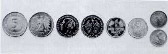 Figure 21. (DKI A 4067) Former German coins of CuNi25
Only occasionally are Cu-Ni alloys with smaller nickel content used for coinage purpose – and then with further additions. Nickel or copper coins plated with CuNi25 are also in circulation. The former German 2 and 5 DM pieces consisted of a three-layer material: CuNi25 on either side of a pure nickel core. This gives defined magnetic properties that are used to differentiate them from counterfeit and foreign currency in coin checkers and thus increases the security of automatic machines. For 1 and 2 Euro pieces, a brass ring is added as third material.
A further application of binary Cu-Ni alloys is in electrical engineering, in which alloys containing 2 to 10% Ni (see Table 3) are used in the manufacture of heating cables with low heating conductor temperature for dynamo slip rings, anodes for TV tubes, low-resistance electrical resistors etc. (see Table 20).
In addition, binary Cu-Ni alloys are used along with materials alloyed with manganese and iron in measuring instruments, aircraft and automobile construction, building, sheet and metal goods industries.
The manganese-containing Cu-Ni alloys are primarily used in electrical engineering as materials for electrical resistors; here CuNi44 is by far the most important alloy. It is used so much because its resistivity of 0.49 Ω . mm2/m reaches a maximum and the associated temperature coefficient is a minimum at this composition (see Table 8 and Fig. 9). CuNi44 is used for resistors whose resistance must vary as little as possible with temperature fluctuations, for precision resistors of all types, measurement resistors, series resistors for measuring instruments, shunt resistors for ammeters, as well as tubular, slide and fixed resistors, for heating units in switching units, for cascading resistors with strip or wire winding, for resistance fabrics in load, testing and heating units and for contact point resistors (Figs. 22 and 23).
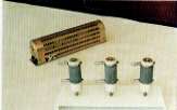 Figure 22. (DKI A 4967) Sliding and fixed resistors of CuNi44 for laboratory and general applications
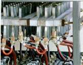 Figure 23. (DKI A 4968) Cascading Resistor with strip winding of CuNi44
 Figure 24. (DKI A 4978) Heating mat with corrugated steel sheath; resistance stranded conductor of CuNi44
The upper application limit for CuNi44 is 600 °C (see Table 8). This resistance material is used for heater elements where a basic requirement is protection from corrosion damage, e.g. for electric heating pads. Heating mats are also made from this alloy (electric panel heating for rooms and open spaces) (Fig. 24).
In addition, CuNi44 is used for thermocouples and as mounting material for electron tubes. This material has a high thermoelectric power versus copper and iron (see Fig. 11) and is therefore also utilised as the negative limb of corresponding thermocouples for temperature measurements in the moderate temperature range. A further advantage is that adherent oxide coatings giving excellent electrical insulation can be produced on finished wire and strip of CuNi44.
CuNi30Mn to DIN 17 471 (upper application limit 500 °C) has a lower resistivity than CuNi44 (see Table 8) and the associated temperature coefficient is larger. This material is used wherever a specific increase of resistance with temperature is required or plays no role, e.g. starting, regulating, control and load resistors.
The alloys CuNi9Sn2 and CuNi5AlMn2 (Table 12 and Table 21) are other interesting materials for electrical engineering.
| Group | Material identification symbol | Particular characteristics | Notes on applications |
|---|---|---|---|
| Wrought Cu-Ni alloys | CuNi5Al4Mn2 | Age-hardenable, wear-resistant, non-magnetic, good workability, high hot strength, seawater-resistant | Pipelines (condenser tubes), current-carrying springs, electromagnetic switches, navigation and measuring instruments |
| CuNi30Cr | Age-hardenable, seawater-resistant, erosion and cavitation-resistant | Condensate tubes and plates; shipbuilding, desalination plant | |
| Cast Cu-Ni alloys | CuNi14Mn10Fe5-C | High strength, resistant to seawater and chloride-containing solutions | Fittings for shipbuilding and marine engineering |
| CuNi30Cr2Mn1-C | As CuNi14Mn10Fe5-C, but with higher strength and age-hardenable | As CuNi14Mn10Fe5-C | |
| CuNi30Be-C | As CuNi30Cr2Mn1-C | As CuNi14Mn10Fe5-C |
CuNi9Sn2 is used in electrical engineering for sprung contacts, relays, light-current switches and plug connectors. This alloy exhibits outstanding relaxation characteristics. Fig. 25 shows examples of applications for this alloy.
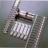 Figure 25. (DKI A 3252) Resilient parts of CuNi9Sn2
CuNi5Al4Mn2 is also a good spring material, which can be used in many circumstances, e.g. in electromagnetic switches, navigation and measuring instruments.
The essential areas of application of iron-containing Cu-Ni alloys are indicated by their high corrosion and erosion resistance in aqueous media. In particular, the alloys CuNi10Fe1Mn and CuNi30Mn1Fe have become interesting materials especially for shipbuilding, power station and heat exchanger construction and for seawater desalination plants.
CuNi10Fe1Mn was developed as an alloy with a lower nickel content for economic reasons and has proved its suitability as a pipe material. As requirements for corrosion resistance become more severe, ships are more and more being equipped with condensers and seawater lines of CuNi10Fe1Mn.
CuNi30Mn1Fe is used as pipe material, particularly in fast-flowing seawater.
The alloy CuNi30Fe2Mn2 is suitable, among other applications, for abrasive liquids, e.g. in dredgers.
CuNi30Cr (see Table 21) is an alloy for more demanding requirements for strength and resistance to erosion corrosion.
The cast Cu-Ni alloys CuNi10Fe1Mn1 and CuNi30Fe1Mn1NbSi are used for pumps and valves in seawater cooling systems of ships and coastal power stations, seawater desalination plant and in the chemical industry (see Table 20), because of their excellent resistance to seawater and other chloride-containing solutions, at the same time having medium to high strength and very good weldability. In many cooling circuits in which wrought Cu-Ni alloys are employed, they act as fittings materials. It is thus possible to use materials of the same type and thereby to gain protection from corrosion and the formation of galvanic couples. The high-strength cast Cu-Ni alloys (see Table 14) have been developed especially for marine purposes (see Table 21). A small summary, arranged by area of application (supplemented by a few pictorial examples) is given in the following.
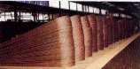 Figure 26. (DKI A 4969) Tube of CuNi10Fe1Mn; processed to tube bends, expandable (size: 17 x 1)
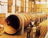 Figure 27. (DKI A 4970) Seawater inlet pipe for the firewater system of Jeddah airport in Saudi Arabia
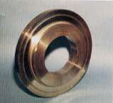 Figure 28. (DKI A 4979) Disc of CuNi14Al3 for manufacture of a compressor impeller, forged and rough turned (size: 450/150 mm dia., 80 mm thick)
Iron-containing Cu-Ni alloys are the preferred piping materials in shipbuilding and harbour installations for seawater, brackish water and deck steam lines (Fig. 26.). They are also used for intakes (Fig. 27), ships’ shafts, rings and discs (Fig. 28), for hydraulic plant (Fig. 29), for plates, bases and tubes of heat exchangers and condensers. Valves, pump bodies, fittings, flanges (Fig. 30), solder fittings (Fig. 31) and small items of Cu-Ni alloys have proved to be best throughout shipbuilding (merchant ships, ferries, passenger ships, naval craft and tankers), because of their resistance to seawater. Cu-Ni alloys also serve as materials for firewater systems, lifeboat cladding etc.
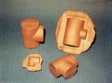 Figure 29. (DKI A 4980) Die forged parts of CuNi10Fe1Mn for manufacture of T and angle pieces for hydraulic systems in marine applications (weights: 0.8 to 2.9 kg)
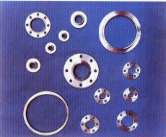 Figure 30. (DKI A 4354) Flanges of CuNi30Mn1Fe, weights 0.5 to 10 kg
The proven operating performance of Cu-Ni alloy pipelines on ships and other marine equipment has led to them recently finding greater application in the offshore industry. Fig. 32 shows seawater pipeline systems on an offshore platform.
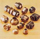 Figure 31. (DKI A 4981) Braze fittings of CuNi10Fe1Mn for offshore engineering
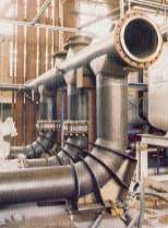 Figure 32. (DKI A 4971) Seawater piping system of CuNi10Fe1Mn on Texaco TARTAN A platform
Because of its fouling-prevention characteristics and good resistance at the water-atmosphere zone, CuNi10Fe1Mn sheet has potential for the cladding the hull of ships (Fig. 33). While steel sheet becomes rougher with use, it actually decreases on CuNi10Fe1Mn. By preventing fouling and increasing the smoothness of a ship’s hull, substantial fuel savings are obtained at the same speed and maintenance costs are less. The cladding of platform legs with CuNi10Fe1Mn to avoid corrosion and fouling has proved to be an excellent measure [21, 22].
 Figure 33(a).
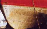 Figure 33(b). (DKI A 4893 and 4897) Hull of CuNi10Fe1Mn-clad sheet before launching (a) and after 2.5 months exposure in the Adriatic sea (b)
In general plant, power station and heat exchanger construction, Cu-Ni alloys in the form of sheet, tube, including finned tube and crimped tube (Figs. 34 to 36), extruded and forged components together with castings are outstanding materials for cryogenic vessels and superheaters, for low-temperature, high-pressure and steam boiler fittings, for condenser tubes and plates in power plant and oil refineries, for nuts, pump parts, hot steam valves and for heat exchanger tubes and plates (Figs. 37 and 38).
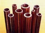 Figure 34. DKI A 4216) Finned tube of CuNi10Fe1Mn and CuNi30Mn1Fe for swimming batch heaters, refrigerant condensers, oil coolers etc.
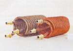 Figure 35. (DKI A 4087) Finned tube coils for hot water production in boilers and tanks; fin height 3.5 mm; materials Cu-Ni alloy containing 5% Ni (left) and SF-Cu
In seawater desalination plant, Cu-Ni alloys are the given materials for evaporator tubes and other parts and in the form of thin dimpled sheet for water chambers.
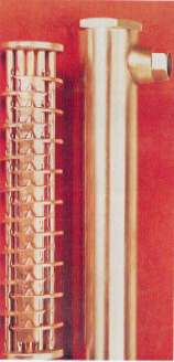 Figure 36. (DKI A 4973) Heat exchanger with novel crimped tube for swimming bath installations; materials: shell, tubes and tubeplates of CuNi10Fe1Mn
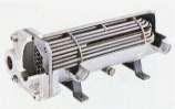 Figure 37. DKI A 4217) Seawater and brackish water-resistant tube bundle oil heat exchanger for ship's gearbox. Seawater flows into the shell space and around the tubes. Gear oil flows through the tubes. Tubeplates, tubes (8 x 1 mm), deflector plates, shell with connection stubs and bottom flap valve consist of CuNi30Mn1Fe; overall length approx. 400 mm; dia. approx. 120 mm
Mechanical engineering also uses iron-containing Cu-Ni alloys for heat exchangers, steam condensers, air and oil coolers (Fig. 45). Feedwater heaters, high-pressure superheaters, seawater evaporators and for preheaters and superheaters in power stations, as non-standard cast and wrought materials with higher iron contents and other additions for turbine blades (5-8% Fe), worm and gear wheels (with Al and other additions), brazing alloys for high chromium steels (approx. 10% Ni + 5% Fe, remainder Cu), materials for permanent magnets (approx. 20% Ni + 20% Fe, remainder Cu) (see 2.1) etc.
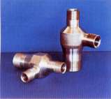 Figure 38. (DKI A 4356) T-piece of G-CuNi30 (now CuNI30Fe1Mn1NbSi-C) for high-pressure technology; cast and machined; weight approx. 40 kg
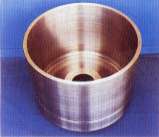 Figure 39. (DKI A 4358) Centrifuge bodt opf G-CuNi30 (now CuNI30Fe1Mn1NbSi-C) for seawater desalination plant; cast and rough turned; weight approx. 250 kg
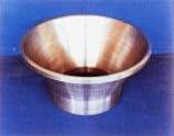 Figure 40. (DKI A 4359) Cone of G-CuNi30 (now CuNI30Fe1Mn1NbSi-C) for seawater desalination plant; cast and rough turned; weight approx. 110 kg
In automobile and aircraft construction, intercoolers and oil coolers (Fig. 46) and honeycomb radiators of iron-containing Cu-Ni alloys are used. Some automobile manufacturers, e.g. Porsche and Volvo, use CuNi10Fe1Mn corrosion-resistant tubes in production for automobile brake lines (Fig. 47). In addition, retro-fit sets of CuNi10Fe1Mn are available on the market for various automobile types. The service life of CuNi10Fe1Mn brake lines generally exceeds the expected life of the motor vehicle.
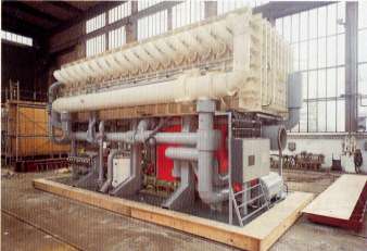 Figure 41. (DKI A 1221) Evaporator plant for fresh water production with an output of 500 m3/day. Condenser tubes, tubes of final heater, partition walls, housing, distillate troughs; all lines through which seawater passes and other important parts of the evaporator consist of CuNi10Fe1Mn
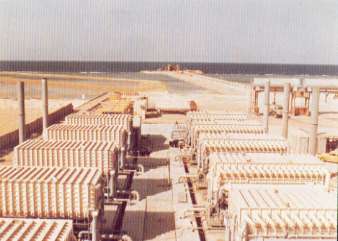 Figure 42. (DKI A 1226) Seawater desalination plant in Jeddah (Saudi Arabia) with an output of 10 x 500 m3 = 5000 m3/day. All lines through which seawater passes, condensers, partition walls, tubes of final heater, housing, distillate troughs; and other important parts consist of CuNi10Fe1Mn
The chemical industry, in which standard and non-standard iron and manganese-containing Cu-Ni alloys are also increasingly gaining acceptance, requires Cu-Ni alloy sheet, tube and castings in oil refineries, for gate valves, valves, valve body seats, covers, shafts and rings and other highly stressed shut-off units subject to corrosion and wear, for pump bodies, impellers, and for thrust rings, for pipelines for salt and other aggressive solutions, for heat exchangers (tubes and tubeplates and interior components), for vessels and tanks, mixers and presses, autoclaves, distillation equipment and fittings, for stirrers (vessels, shafts, distributor blades and other individual parts) as well as for many other items of equipment.
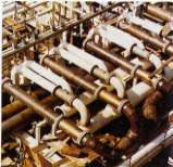 Figure 43. (DKI A 4974) Seawater cooling pipe system of CuNi10Fe1Mn (outside diameter 610 mm or 508 mm) for the TCP2 compression plant of "e;Frigg Field"
Paper mills, printing works and the textile industry make use of Cu-Ni alloys in the form of vessels, pipes and pipe fittings for pulps and liquids, for, for corrosion-resistant castings and forgings, rolls for paper processing etc.
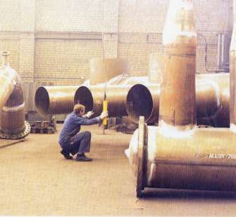 Figure 44. (DKI A 4975) Seawater piping system of Cu-Ni alloys for the YANBU seawater desalination plant in Saudi Arabia
In the food industry, Cu-Ni alloys are used in especially highly-stressed multi-stage evaporators, in sugar refineries, in feedwater heaters and stirrer vessels, in lines and plant for packing, conveying and processing foodstuffs, for fruit juice filters, sieves, mixers and presses as well as pipelines of all kinds.
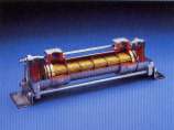 Figure 45. (DKI A 4976) Round tube heat exchanger for cooling oil, water, slow-burning liquid or emulsion by industrial, sea, river or brackish water; cooling tubes of Cu-Ni alloys
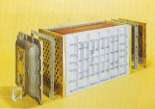 Figure 46. (DKI A 4977) Intercooler (water and air-cooled); cooling tubes of Cu-Ni alloys
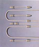 Figure 47. (DKI A 878) Automobile brake lines of CuNi10Fe1Mn
REFERENCES
- Legierungen des Kupfers mit Zinn, Nickel, Blei und anderen Metallen (Fachbuch). Deutsches Kupfer- lnstitut, Berlin 1965
- F. Pawlek: Metallhtlenkunde, Walter de Gruyter, Berlin-New York 1983
- E. A. Brandes: Smithells Metals Reference Book, Sixth Edition, Butterworth & Co 1983
- Ullmann's Encyclopedia of Industrial Chemistry, Fifth Edition, Weinheim 1986
- Werkstoff-Handbuch Nichteisenmetalle. Tell III Cu. VDI-Verlag Dsseldorf 1960
- K. E. Volk und H. Holetzko: Nickel-Kupfer-Legierungen - Knetlegierungen mit weniger als 50 % Ni. In Landolt-Brnstein, "Zahlenwerte und Funktionen". IV. Bd., 2. Tell, Bandteil b, S. 398/412. Springer-Verlag, Berlin 1964
- Kupfer-Nickel-Legierungen. Nickel-Informationsbro GmbH, Dsseldorf 1964
- F. Richter: Physikalische Eigenschaften von CuNi10Fel Mn und CuNi30Mnl Fe unter besonderer Berucksichtigung des Ausscheidungsverhaltens. Z. Werkstofftechn. 17 (1986), S. 273-280
- K. Dies: Kupfer und Kupferlegierungen in der Technik. Springer-Verlag, Berlin 1967
- Kupferwerkstoffe. Wieland-Werke AG Metallwerke Ulm, 1986
- B. Weldon, E. Weisner: Eigenschaften und Anwendungen von Kupfer-Nickel-GuBlegierungen. Schiff und Hafen 25 (1973), S. 785-791
- C. H. Thornton, S. Harper und J. E. Bowers: A critical survey of available high temperature mechanical property data for copper and copper alloys - Incra Monograph Xli, The Metallurgy of Copper, New York 1983
- Copper Data Sheet No K2, K5-K7, CIDEC, Gnve 1972
- Metals Handbook, 9th Edition, ASM, Metals Park, Ohio 1981
- J. P. Chubb, J. Billingham u. a.: Effect of alloying and residual el- ements on strength and hot ductility of cast cupro-nickel. J. Metals, March 1978, S. 20-25
- Richtwerte fr die spanende Bearbei- tung von kupfer und Kupferlegierun- gen. Informalionsdruck i. 18, Deutsches kupfer-Institut, Berlin 1983
- SchweiBen von Kupfer und Kuplerle- gierungen (Fachbuch). Deutsches Kupfer-Institut, Berlin 1978
- Guide to the welding of copper-nickel alloys. INCO Europe Ltd. 1979
- F. Richter und H. Ldorff: Heirianflligkeit und magnetische Permeabilitt beim Werksloff CuNi10Fe. Schweif3en und Schneiden 38 (1986) 2, S. 80 ff.
- German standard - VG 81245, Teil 3 (03.91): Nichteisen-Schwerme- talle; Schweitzustze und Hartlote, Auswahl
- Kupfer-Nickel-Bekleidungen fr Offshore- Plattformen. Sonderdruck s. 202, Deutsches Kupfer-Institut und Copper Development Association, 1986
- D. G. Melton: Review of Five-Year Exposure Data for CuNi-Sheathed Steel Pilings. OTC, Houston-Texas, May 6-9(1991), pp 221-223.
ILLUSTRATION CREDITS
- Deutsche Bundesbank, 6000 Frankfurt/M: 21
- Platthaus Elektrotechnik, 5653 Leichlingen 2: 22, 23
- Kabeimetal Electro, 3000 Hannover 1: 24
- Wieland-Werke AG, 7900 Ulm: 25, 34
- H. D. Eichelberg & Co. GmbH, 5750 Menden 1: 26
- Vereinigte Deutsche Metallwerke AG, 5980 Werdohl: 27, 31, 32, 44
- Zollern Stahl und MetalI GmbH & Co., 7480 Sigmaringen: 28, 29
- Vereinigte Deutsche Nickeiwerke AG, 5840 Schwerte: 30, 38, 39, 40
- Thyssen Stahl AG, 4100 Duisburg: 33
- R. & G. Schmle, 5750 Menden 1: 35, 36