- Introduction
- Shielded Metal Arc Welding
- Gas Metal Arc Welding
- Gas Tungsten Arc Welding
- Resistance Welding
- Brazing
- Soldering
- Dissimilar Metal Joining and Weld Overlaying
- Cutting
- Welding Cu-Ni Clad Steel Plates
- Sheet Lining
- Pipe Welding
- References
Introduction
Cu-Ni alloys find many applications in marine, power, electrical and chemical industries. Typical hardware fabricated by welding are condenser and heat exchanger components, seawater piping, distillation apparatus and, demonstrating the excellent antifouling qualities of Alloy UNS C70600, the hull of an ocean going commercial fishing vessel, the Copper Mariner. The composition of common Cu-Ni alloys and filler metals is shown in Table 1.
| Composition, % maximum unless shown as a range or minimum | ||||||||
|---|---|---|---|---|---|---|---|---|
| UNS Alloy No. | Previous Trade Names | Cu | Ni | Pb | Fe | Zn | Mn | Other Named Elements |
| C70400 | Cu-Ni, 5% | Rem. | 4.8 - 6.2 | .05 | 1.3 - 1.7 | 1.0 | .3 - .8 | |
| C70600 | Cu-Ni, 10% | Rem. | 9.0 - 11.0 | .05 | 1.0 - 1.8 | 1.0 | 1.0 | |
| C71000 | Cu-Ni, 20% | Rem. | 19.0 - 23.0 | .05 | 1.0 | 1.0 | 1.0 | |
| C71500 | Cu-Ni, 30% | Rem. | 29.0 - 33.0 | .05 | .4 - .7 | 1.0 | 1.0 | |
| C72500 | Cu-Ni, Tin | Rem. | 8.5 - 10.5 | .05 | .6 | .5 | .2 | 1.8 - 2.8 Sn |
| ERCuNi(a) (C71580) |
Rem. | 29.0 - 32.0 | .02 | .4 - .75 | (c) | 1.0 | .25 Si .02 P .2 - .5 Ti |
|
| ECuNi(b) (W60715) |
Rem. | 29.0 - 33.0 | .02 | .4 - .75 | (c) | 1.0 - 2.5 | .5 Si .02 P .5 Ti |
|
| (a) ANSI/AWS 5.7-84 (b) ANSI/AWS A5.6-84 (c) Total of lead, zinc, tin and all other elements not named shall not exceed 0.50%. |
||||||||
Most alloys of Cu-Ni are solid solutions as shown in Figure 1. They may be work-hardened to tensile strengths above the 60 Ksi (410 MPa) level. Typical annealed properties are of 15-20 Ksi (100-140 MPa) yield strength and 40-50 Ksi (275-350 MPa) tensile strength. Alloy C71900 has alloying additions which enables it to be heat treated to a tensile strength of 80 Ksi (550 MPa) and above. The Cu-Nis may be used in the work hardened condition as they are highly resistant to stress corrosion.
 Figure 1. Cu-Ni phase diagram
While copper and nickel are mutually soluble with each other as shown in Figure 1, a number of other elements are not soluble in the Cu-Ni alloy and if present may cause cracking in the heat affected zone (HAZ) or weld metal. Lead, sulfur and phosphorus are particularly detrimental and may cause intergranular hot cracking in highly restraint joints. (1) It is essential that the surfaces be clean and free of these contaminating elements before heating to a high temperature such as in annealing or welding.
Common sources of the contaminating elements sulfur and phosphorus are marking crayons, paints, temperature indication markers, cutting fluids, oil and grease. Oil- or grease-base contaminants must be removed by solvent cleaning. Acceptable methods include immersion in, swabbing with or spraying with alkaline, emulsion, solvent or detergent cleaners or a combination of these; by vapor degreasing; by steam, with or without a cleaner; or by high-pressure water jetting.
A typical procedure to remove oil or grease prior to welding includes:
- remove excess contamination by wiping with clean cloth
- swab the weld area (at least 2 in. [5 cm] each side of the weld) with an organic solvent such as aliphatic petroleums, chlorinated hydrocarbons or blends of the two. Use only clean solvents (uncontaminated with acid, alkali, oil or other foreign material) and clean cloths
- remove all solvent by wiping with clean, dry cloth
- check to assure complete cleaning. A residue on the drying cloth can indicate incomplete cleaning.
All the commonly used welding processes are applicable to the Cu-Ni alloys. A nominal 70-30 Cu-Ni filler metal with titanium as a deoxidizer is almost invariably used to weld all of the Cu-Ni alloys. A 90-10 Cu-Ni bare filler metal and a covered electrode is available in Europe and occasionally used, but the bare wire is generally limited to gas tungsten arc welding (GTAW) gages up to 0.125-in. (3-mm) thick. Welds made with 90-10 Cu-Ni fillers should be limited to non-wetting surfaces since the weld may be anodic to the base metal. Guides for the various welding processes follow.
Shielded Metal Arc Welding
For shielded metal arc welding (SMAW), the flux covered electrode ECuNi is used with direct current electrode positive (reverse polarity). If the arc length is kept short, the weld pool can be controlled in all positions with a 3/32- or 1/8-in. (2.4- or 3.2-mm) diameter electrodes. Long arc lengths should be avoided because of the tendency to cause weld metal porosity. The electrodes should be operated within the manufacturer's recommended current ranges. Excessive amperages will result in weld spatter and undercut at the edge of the weld, especially when the base metal melting point is significantly below that of the filler.
Weld defects are more likely to occur at arc starts and stops. In starting the arc, the proper technique is to strike the arc at some point in the joint so that the metal is remelted. In completing a pass, the arc should not be abruptly extinguished leaving a large weld crater. One acceptable technique is to hold the arc over the weld pool for a few moments and then move quickly back, lifting the arc from the completed weld.
An open root gap and wide groove angle improves penetration and assures good fusion. Tack welds at least every six inches are needed to maintain the opening.
A square-groove preparation for plate up to 1/4 in. (6.4 mm) has been used for flat position welding as shown in Table 2. The more common practice is to limit the square-groove to 1/8 in. (3.2mm) with a root opening at least half the sheet thickness. For out-of-position welding, beveled grooves are required. The procedures presented in Table 2 were used for joining 1/4-in. hull plates of Alloy C70600 by the SMAW process. The current settings shown may be useful as a guide in establishing parameters for other jobs. The proper setting will also depend on the nature of the duty cycle and power source.
| Position | Downhand | Vertical(b) | Horizontal | Downhand (1st pass) Overhead (2nd pass) | Vertical(b) |
|---|---|---|---|---|---|
| Edge perforation(c) |  |
 |
|||
| Gap, in. | 1/8 | 3/32 - 1/8 | 1/16 - 1/8 | 3/32 - 1/8 | 3/32 |
| Number of passes | 2 | 2 | 2 | 2 | 1 or 2 (d) |
| Filler size, in. | 1/8 | 3/32 | 3/32 (1st pass) 1/8 (2nd pass) |
1/8 (1st pass) 3/32 (2nd pass) |
3/32 |
| Current amps | 115 - 120 | 85 - 90 | 100 (1st pass) 100 (2nd pass) |
100-115 95-100(2nd pass) |
85 |
| (a) ECuNi electrode (b) Welding uphill (c) Backgouge to a wide V between passes. Tack weld every six inches to hold gap. (d) Where accessibility permitted, one pass was made on each side |
|||||
Both stringer and weaving techniques are successful with Cu-Ni alloys. However, weaving is usually necessary for vertical uphill and overhead position welding. Weaving should be limited to no more than three times the core wire diameter.
Between passes, surfaces should be cleaned of flux by chipping and/or grinding. When backgouging in preparation for welding from the opposite side, it is essential to gouge to sound metal and to prepare a wide (80° to 90°) V-groove.
Gas-Metal Arc Welding
Cu-Ni alloys are welded with the GMAW process using deoxidized filler metal and direct current reverse polarity. Argon or mixtures of argon and helium at flow rates of 25-50 ft.3/h (0.75 - 1.5 m3/h) are usually used. Spray transfer is generally used for 1/4-in. (6.4-mm) thick and heavier sections, but the process is limited to the flat position. For welding sheet and plate from one side, grooved copper or Cu-Ni backing bars are preferred.
Representative parameters used in joining Cu-Ni alloys by GMAW spray arc are shown in Table 3. Currents on the high side of the range are favored for the higher conductivity, lower nickel content alloys. Stringer beads and thin layers to minimize heat input are usually beneficial.
| 1/16 in. ECuNi filler, direct current, reverse polarity | ||||||
|---|---|---|---|---|---|---|
| Thickness (inches) | Edge Preparation | Gap (in.) | Voltage (volts) | Current (amps) | Wire Feed (in. per min.) | Argon Flow (cfh) |
| 1/8 | square butt | 0 | 22 - 28 | 270 - 300 | 180 - 200 | 20 - 30 |
| 1/4 | square butt or single V-60° | 1/16 - 1/8 | 22 - 28 | 270 - 300 | 180 - 200 | 20 - 30 |
| 3/8 | single V-60° | 0 | 22 - 28 | 300 - 360 | 200 - 240 | 20 - 30 |
| 1/2 | single or double V-60°, 1/16 in. face |
0 | 22 - 28 | 350 - 400 | 220 - 240 | 20 - 30 |
| 3/4 | double V-60°, 1/16 - 1/8 in. face |
0 | 24 - 28 | 350 - 400 | 220 - 240 | 30 - 50 |
| 1 | double U, 1/16 - 1-8 in. face | 0 | 26 - 28 | 350 - 400 | 220 - 240 | 30 - 50 |
| >1 | double U, 1/16 - 1/8 in. face | 0 | 26 - 28 | 370 - 420 | 240 - 260 | 30 - 50 |
The ERCuNi filler composition provides welds equivalent in strength to C71500 base metal and greater in strength than C70600. ERCuNi contains 0.20% to 0.50% Ti, which serves as a deoxidizer to prevent porosity and oxygen embrittlement.
Short circuit (GMAW-S) is a relatively low heat input process using 0.035- or 0.045-in. (0.8- or 1.2-mm diameter) filler metal and is well suited to weld gages under 1/4 in. (6.4mm). Argon shielding may be used, but argon-helium mixture gives better wetting and better bead contour. The low heat input allows welding in all positions.
Pulsed arc (GMAW-P) incorporates many advantages of both spray arc and short circuit transfer and is well suited for welding C70600 and C71500 alloys. The electrode diameter is usually 0.045 in. (1.2mm) and an argon-helium mixture shielding gas gives good wetting and arc action. GMAW-P is adaptable to welding in all positions. A more recent advancement in pulsed welding is synergic or variable pulsed welding. With synergic welding, the welder has fewer welding variables to set and there is an improvement in weld quality.
One observation often made when first GMA welding with ERCuNi filler metal is that the wire temper is noticeably lower than that of iron- or nickel-base fillers. Cu-Ni alloys do not work harden to nearly the same degree so the temper is usually lower. To minimize wire feeding difficulties, low friction cable liners should be used.
Gas Tungsten Arc Welding
The GTAW process is the preferred process for welding thin gage material, 1/16 in. (1.6mm) and less, but can be a good choice for gages up to about 1/8 in. (3.2mm). The all-position operability characteristic makes it an excellent process for pipe welding, particularly for small diameter pipe and the root pass of all pipe diameters. After a GTAW root pass in heavier pipe, the weld is often completed by GMAW or SMAW. Automatic GTAW equipment is available for applications such as tube to tube sheet welds, orbital pipe welding and joining sheet gages.
Cu-Ni welds made without the addition of the deoxidized filler material very often have excessive porosity that is not apparent on the weld surface. For this reason autogenous GTA welds should be avoided. Other good welding practices to avoid porosity include a short arc, about 0.03 inches (0.8mm) and ample weld metal shielding to exclude air from the molten weld metal. Argon is the usual shielding gas and preferred for purging the inside of pipes during root pass welding.
Representative parameters for GTAW Cu-Nis are shown in Table 4. As with the other arc welding processes, the high conductivity, lower nickel alloys require currents on the high end of the range. Where possible, copper or Cu-Ni backing bars are favored.
| ERCuNi filler, direct current, straight polarity | ||||
|---|---|---|---|---|
| Thickness (in.) | Electrode Size (in.) | Filler Wire (in.) | Current (amps) | Argon Flow (cfh) |
| 1/16 | 1/8 | 1/16 | 100 - 140 | 15 - 20 |
| 1/8 | 1/8 | 1/8 | 140 - 200 | 15 - 20 |
| 1/4 | 1/8 | 1/8 - 3/16 | 180 - 260 | 20 - 30 |
| 3/8 | 1/8 - 3/16 | 1/8 - 3/16 | 260 - 320 | 20 - 30 |
| 1/2 | 3/16 | 1/8 - 3/16 | 320 - 400 | 20 - 30 |
Resistance Welding
Cu-Ni alloys with 10% ore more nickel content have good to excellent spot and seam welding characteristics due to their low thermal and electrical conductivity compared to copper. Precautions must be taken to assure that surfaces to be resistance welded are clean and free from contaminants.
Brazing
Cu-Ni alloys are most often brazed with silver-base brazing alloys. Fillers of AWS A5.8 Classifications BAg-1a, BAg-2, BAg-18 and BAg-5 are ordinarily used. Alloys BCuP-5 and BCuP-3 are acceptable for use with Cu-Nis of 10% or less nickel. The corresponding UNS numbers are shown in Table 5. They should not be used for alloys with high nickel content due to the possibility that embrittling nickel phosphides will be formed. Copper-phosphorus brazing alloys should not be selected for service in sulfurous atmospheres.
| AWS A5.3 Classification | BAg-1a | BAg-1 | BAg-2 | BAg-5 | BAg-18 | BCuP-3 | BCuP-5 |
|---|---|---|---|---|---|---|---|
| UNS Number | P07500 | P07450 | P07350 | P07453 | P07600 | C55281 | C55284 |
Fluxes of the AWS types FB3-A, C, E are satisfactory for most applications. For furnace brazing, inert gases, exogas, endogas or disassociated ammonia are suitable. The dew point should not exceed 20°F (-7°C). For torch brazing, a neutral flame is used. Brazing clearances of 0.001 in. to 0.005 in. (0.03 mm to 0.13 mm) produces maximum joint strength and soundness.
Molten braze alloys may penetrate and crack Cu-Ni alloys that are not stress relieved prior to brazing. Also surfaces should be mechanically or chemically cleaned before brazing. Emery paper is usually satisfactory on pipe and tube. Solvents or alkaline cleaners should be used to remove grease and oil. An effective procedure for pickling to remove oxides is as follows: dip in 5% sulfuric acid at 180°F to 200°F (82° C to 93° C) and rinse immediately.
After brazing, any flux residues should be removed by washing with hot water. Oxides may be removed with the same pickling solution used for cleaning prior to brazing.
Soldering
Preparation for soldering is the same as for brazing. Cu-Ni alloys have good solderability when an active chloride type flux is used. It may be of the mildly corrosive glutamic acid-hydrochloride type or stronger mixtures of zinc, sodium and ammonium chlorides. Lead-tin and tin-antimony solders are used for Cu-Ni alloys. Cu-Ni alloys are classed as somewhat less solderable than brasses.
Dissimilar Metal Joining and Weld Overlaying
Suggested filler metal for joining Cu-Ni alloys to some of the commonly combined other alloys is shown in Table 6. The listing is not intended to be exclusive in that welding procedures could be developed using filler metals not listed.
| Metal to be joined to Cu-Ni | SMAW (UNS) | GMAW and GTAW (UNS) | Comments |
|---|---|---|---|
| ANSW/AWS A5.6 | ANSI/AWS 5.7 | ||
| Copper | ECuNi (W60715) or ECuA1-A2 (W60614) |
ERCuA1-A2 (71580) or ERCuA1-A2 (C61800) |
Preheat to 1000°F (540°C) |
| Phosphor bronzes | ECuSn-A (W60518) | ERCuSn-A (C51800) | - |
| All bronzes | ECuA1-A2 (W60614) | ERCuNl (C61800) | - |
| ANSI/AWS a5.11 | ANSI/AWS A5.14 | ||
| Carbon steel | ENiCu-6 (W84190) | ERNiCu-7 (N04060) | Steel side may be overlayed first with ERNi-1 or ERNiCu-7 |
| Austinetic stainless steels | ENi-1 (W82141) or ENiCrFe-2 (W86133) |
ERNi-1 (N02161) or ERNiCr-3 (N06082) |
Stainless side may be overlayed first with ERNi-1 |
| Metal to be joined to Cu-Ni | SMAW (UNS) | GMAW and GTAW (UNS) | Comments |
|---|---|---|---|
| AWS A5.6 / (BS EN ISO 17777 is under development) | AWS 5.7 / BS EN ISO 24373 | ||
| Copper | ECuNi or ECuAl-A2 | ERCuNi or ERCuAl-A2 / S Cu 7158 or S Cu 6180 |
Preheat to 1000°F (540°C) |
| Phosphor bronzes | ECuSn-A | ERCuSn-A / S Cu 5180A |
- |
| Aluminum bronzes | ECuAl-A2 | ERCuAl-A2 / S Cu 6180 |
- |
|
AWS A5.11 / | AWS A5.14 / BS EN ISO 18274 | ||
| Carbon steel | ENiCu-7 / E Ni4060 |
ERNiCu-7 / S Ni4060 |
Steel side may be overlayed first with ERNi-1 or ERNiCu-7 |
| Austinetic stainless steels | ENi-1 or ENiCrFe-2 / E Ni2061 or E Ni6092 |
ERNi-1 or ERNiCr-3 / E Ni2061 or S Ni6082 |
Stainless side may be overlayed first with ERNi-1 |
The 70-30 Cu-Ni welds have a limited tolerance for dilution by iron. Welds with more than about 10% iron tend to have excessive fissures and develop hot cracks. The ENiCu-7 and ERNiCu-7 fillers (65Ni-Cu) have a higher tolerance for iron and are used in joining to carbon steels. However, they are not a good choice in welding to stainless steels because of limited tolerance for dilution by chromium.
Often a very useful step in making Cu-Ni dissimilar metal welds is to overlay or butter the other metal with nickel, nickel-copper or any other appropriate filler shown in Table 6. In applying Cu-Ni overlays on steel, the usual practice is to apply a first layer with ERNi-1 or ERNiCu-7 and then ERCuNi for subsequent layers. Although a high alloy barrier layer is standard, it is possible to apply ERCuNi by GMAW directly on carbon steel with carefully controlled welding procedures designed to achieve relatively low iron dilution on the first layer.
The submerged arc welding (SAW) process is ideally suited for overlaying large surface areas. Commercial submerged arc fluxes are available for all the nickel, nickel-copper and Cu-Ni filler metals.(3) In overlaying carbon steel, the first layer is applied using either an ERNi-1 or ERNiCu-7 filler metal followed by subsequent layers of ERCuNi to reach the needed thickness or composition.
Brazing with BAg-1a, BAg-1 and BAg-2 is suitable for joining Cu-Ni to any other copper alloy.
Cutting
Cu-Ni alloys are not amenable to flame cutting, but plasma arc cutting and carbon arc cutting work well. Band saws and shears may be used for cutting, but allowances must be made for the fact that the alloys are relatively soft and ductile. High-speed abrasive wheels work well for beveling edges and trimming material.
Welding Cu-Ni Clad Steel Plates
The use of Cu-Ni clad steel plates offers considerable material savings in many designs and applications. An example is the 76-foot (25-m) fishing trawler, Copper Mariner II, with the hull constructed of 5/16-in. (8-mm), 25% C70600 clad. An extensive welding development program was undertaken prior to construction.(4)
For best corrosion performance, the weld face of the alloy side welds should not exceed 10% iron and preferably be below 6% iron. To reach this iron level, at least two weld passes are needed on the alloy side. The alloy side weld filler metals suggested are:
- ENi-1, ERNi-1, ENiCu-7 or ERNiCu-7 for the first or barrier pass from the alloy side on to the backing steel; and,
- ECuNi or ERCuNi filler metal for the top or cover pass(es) on the alloy side. ECuNi and ERCuNi are less noble than ENiCu-7 or ERNiCu-7 and are more compatible galvanically with the Cu-Ni base metal.
 Figure 2. Typical weld joint and bead sequence for Cu-Ni clad steel plate
(1/2- to 3/8-inch or 6.4 to 8.3 mm thick)
- Pass 1 - use ENi-1, ERNi-1, NIiCu-7, or ERNiCu-7 filler; the top of the weld may require grinding to allow room for pass 2
- Pass 2 - Use ECuNi or ERCuNi
- Backgouge carbon steel side to clean metal and provide bevel for accessibility
- Passes 3,4, or as needed: ERNi-1, ENiCu-7, or ERNiCu-7
 Figure 3. Typical weld joint and bead sequence for Cu-Ni clad steel plate, 1/2 inch (12.7 mm) and thicker
- Pass 1, 2 and 3 or as needed - carbon steel fillers such as E7018 or comparable filler for GMAW or SAW
- Backgouge from alloy side to clean metal providing a bevel for accessibility
- Pass 1A - ENi-1, ENiCu-7, or ERNiCu-7; grinding top of the weld may be needed to allow room for pass 2A
- Pass 2A - ECuNi or ERCuNi
A wide range of weld joint designs and weld pass sequences have been used for clad steel welding. Factors that influence the choice include: total plate thickness, alloy thickness, welding process employed, accessibility to one or both sides, composition constraints of the cover pass to name the more important. Two commonly used weld joints and procedures are shown in Figure 2 and Figure 3. Two basic principles that must be observed in welding Cu-Ni clad steel plate are:
- never let the carbon steel weld penetrate the alloy cladding or alloy weld. Steel welds with copper pickup are susceptible to hot cracking. And,
- do not weld with ECuNi or ERCuNi on to steel or exceed about 10% iron in the weld. Welds with higher iron content are susceptible to hot cracking.
Sheet Lining
An alternate to the use of solid Cu-Ni alloy or clad steel is applying relatively thin sheets to a carbon steel backing. C70600 has been sheet lined to steel for such applications as ship hulls, rudders, condenser water boxes and sections of off-shore platforms. The geometry of the surface to be covered and liner thickness dictates to a large extent the lining method.
Figure 3 shows a carbon steel water box lined with 0.048-in. (1.2-mm) thick C70600 Cu-Ni. The liner was first fabricated by GTAW to close tolerances to fit into the carbon steel shell.(5) The liner was anchored to the steel by a number of arc spot welds made by the GMAW process. Arc spot welding is not new and is used to apply other iron- and nickel-base alloys to carbon steel. Basically a standard GMAW torch is adapted with a "stand-off" attachment that is used to press against the liner and to establish the contact tip distance.(6) With preset power source and wire feed parameters, the weld is completed in about one second with additional shielding gas flow time to protect the weld.
Other arc spot weld features and controls include:
- The process can be used on sheet thicknesses of 0.024 in. to 0.078 in. (0.6 mm to 2.0 mm), with 0.048 in. (1.2 mm) being preferred.
- Flat position with intimate contact between sheet and steel backing produces the most reproducible results. With a gap up to the sheet thickness between the sheet and the backing, there is some "flash" of weld metal into the gap, but full strength welds are still realized.
- In vertical position welds, there is a tendency for weld undercut and sagging unless the welding current and welding arc time are carefully controlled.
- Using proper welding parameters, welds have less than about 6% iron on the top surface.
- All surfaces should be free of oil, grease, dirt and oxide scale prior to arc spot welding.
When arc spot GMAW is not practical, for example because of welding position or a heavy gage, mid-sheet attachments can be made by plug welding using precut holes. The holes may be circles or slots, e.g., 1/2-in. (12.4-mm) diameter or 1 in. by 3/8 in. (25 mm by 9.5 mm) slots. Round holes in over about 3/32-in. (2.4-mm) thick sheet should have a tapered side to avoid side wall lack of fusion defects. Slot welds are often easier to weld, particularly when the welding is done on vertical surfaces. In many applications it is also necessary to fillet weld the edges of the sheet to the steel backing. The preferred filler metals for the plug and edge welds are ENiCu-7 or ERNiCu-7.
Pipe Welding
Cu-Ni alloy pipe is widely used in piping systems for shipboard services, coastal installations, desalination plants and offshore oil production. Small diameter pipes, 2.0 in. (50 mm) and under are often socket weld joints. The preferred procedure for larger diameter pipes is a GTAW root pass with the option of GTAW, GMAW or SMAW fill welding. Most consistent quality and higher productivity is obtained when the pipe can be rotated for downhand welding.
The GTAW root pass may be made by manual welding using either the hand-fed filler metal technique or consumable inserts or by using automatic orbital pipe welding. The pipe interior should be purged with argon using the standard practices for other alloys such as stainless steel and nickel alloys. The manual root pass procedures for Cu-Ni are basically the same as for other alloy piping, but the welders may notice the weld metal does not flow as well as an austinetic stainless steel. The pipe joint design for manual welding is usually a V-bevel with a nil root face and root opening. The filler metal is ERCuNi, and the torch shielding gas is argon.
Automatic welding Cu-Ni with orbital pipe welding equipment offers higher production rates and fewer weld defects. On a large firewater system for an offshore platform, orbital welding was able to reduce welding time to one half that of manual welding and cut reject rate from 15% to 5% (7) The joint design tolerances must be tightly controlled and are crucial for successful orbital welding. The recommended joint design for most pipe sizes is a J-groove with a 25° bevel, a 3/32-in. (2.4-mm) radius, an 0.050-in. (2-mm) root face with a 0.03-in. (0.8-mm) extension. Figure 4 shows a weld head mounted on a Cu-Ni pipe and joining a straight section of pipe to a "T" section fitting.
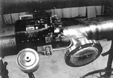 Figure 4. Automatic orbital weld head welding Cu-Ni firewater piping
REFERENCES
- Boundary Cracking in CuNi10Fe Alloy Weldments; Stephenson, Dr. Norman, NiDI Reprint Series No. 14016.
- CA-706 Cu-Ni Alloy Hulls: the Copper Mariner's Experience and Economics; Manzolillo, J.L., Thiele, E.W. and Tuthill, A.H., Trans SNAME, 1984 (1976), p408. (Available from CDA and NiDI.)
- ; A Technical Publication by Inco Alloys International, Inc., Newton, NC.
- Copper and Cu-Ni Clad Plates, Prager, M., Keay, L.K., Thiele, Jr., E.W. Welding Journal, September 1978.
- to the Welding of Cu-Ni Alloys; International Nickel Publication No. 1280, available from NiDI.
- Lining Mild Steel Components with 90-10 Cu-Ni Alloy Sheet; Ridgeway, W.F. and Heath, D.J., Welding and Metal Fabrication, October 1969.
- Orbital Pipe Welding Used on Hondo's Firewater System; Guilsardo, A., Dumas, E., and Henon, B.K., OFFSHORE, April 1993.